
Amplifier device

a technology of amplifier and amplifier, which is applied in the direction of amplifier combinations, amplifier modifications to reduce non-linear distortion, and low-noise amplifiers, etc., can solve the problems of increasing circuit design and cost, limiting the power consumption of amplifier devices, and complicated circuit design correspondingly, so as to facilitate the disclosure of the present disclosure

Active Publication Date: 2019-06-18
RICHWAVE TECH CORP
View PDF8 Cites 0 Cited by
  • Summary
  • Abstract
  • Description
  • Claims
  • Application Information

AI Technical Summary

Benefits of technology

The patent text discusses the limitations of amplifier devices in communication modules due to their non-linear power-gain and power-phase curves. Rather than reducing power or introducing a pre-distortion circuit, the patent aims to address these limitations by developing a more complex circuit design that requires different control factors. The technical effect of this patent is to improve the efficiency and reliability of amplifier devices in communication modules.

Problems solved by technology

Due to the fact that the power-gain curve and power-phase curve of an amplifier device tend to be non-linear when they reach a certain level, amplifier devices are limited in power usage.
Though the approaches of reducing the power or introducing a pre-distortion circuit may be utilized, the complexity of circuit design and cost would increase correspondingly.
Moreover, the linearity of an amplifier device varies according to the input signal, voltage source or temperature, so that if a pre-distortion circuit is utilized as previously described, different control factors need thus be considered, and the circuit design would also become more complicated.
Therefore, providing an amplifier device with simple circuit and capable of self-adjusting linearity becomes a critical issue.

Method used


Image

  • Amplifier device
  • Amplifier device
  • Amplifier device

Examples


Embodiment Construction

[0015]The aforementioned illustrations and following detailed descriptions are exemplary for the purpose of further explaining the scope of the present disclosure. Other objectives and advantages related to the present disclosure will be illustrated in the subsequent descriptions and appended drawings.

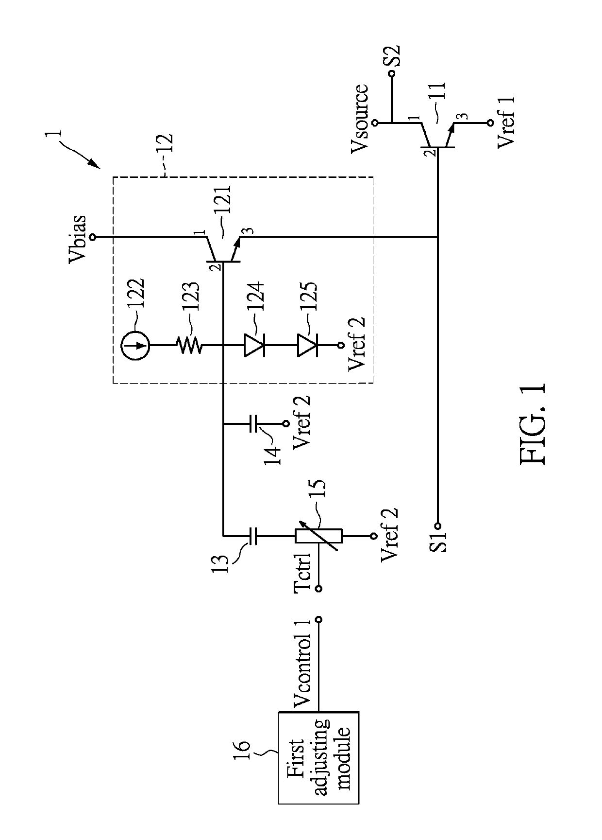
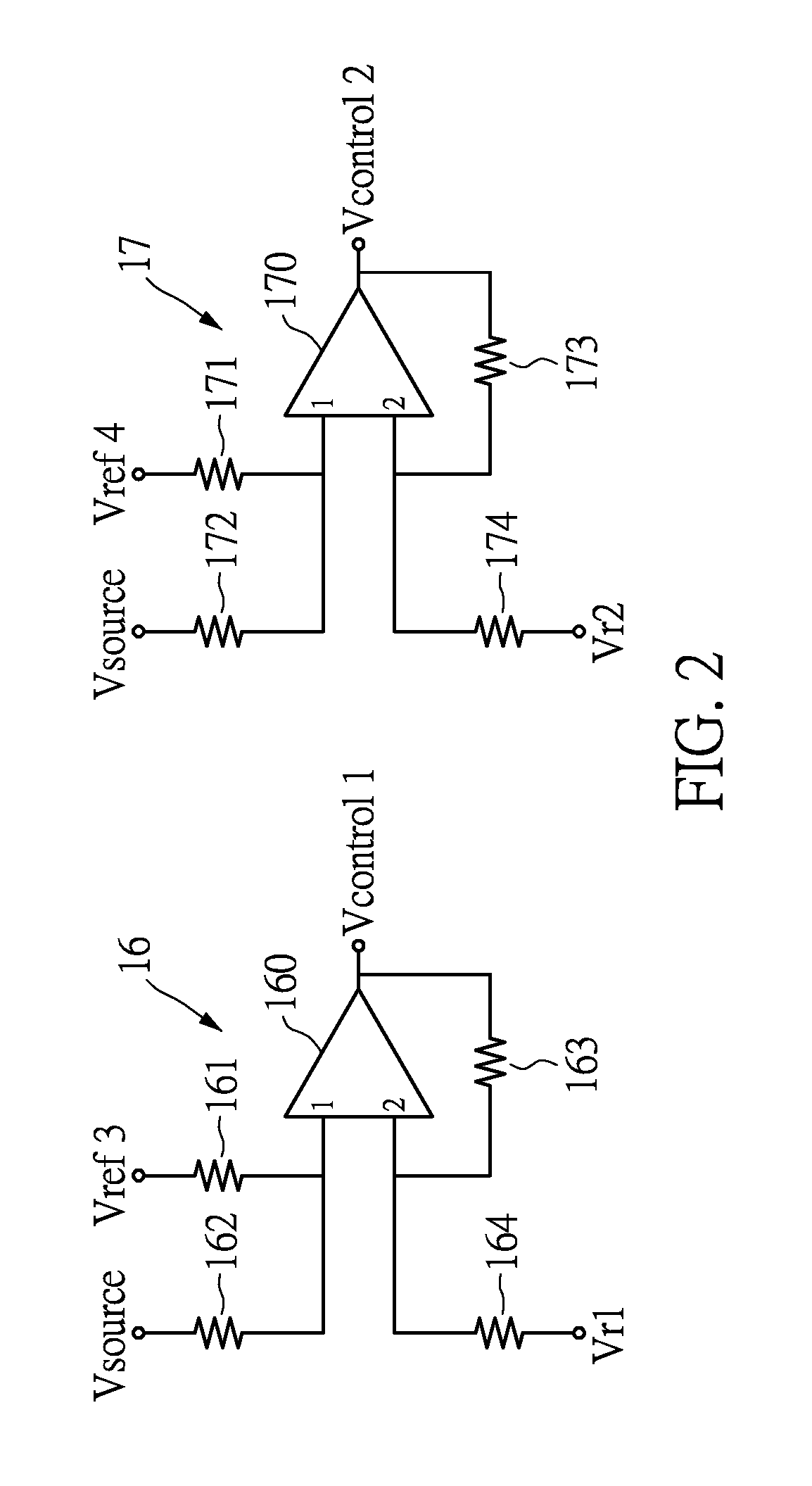
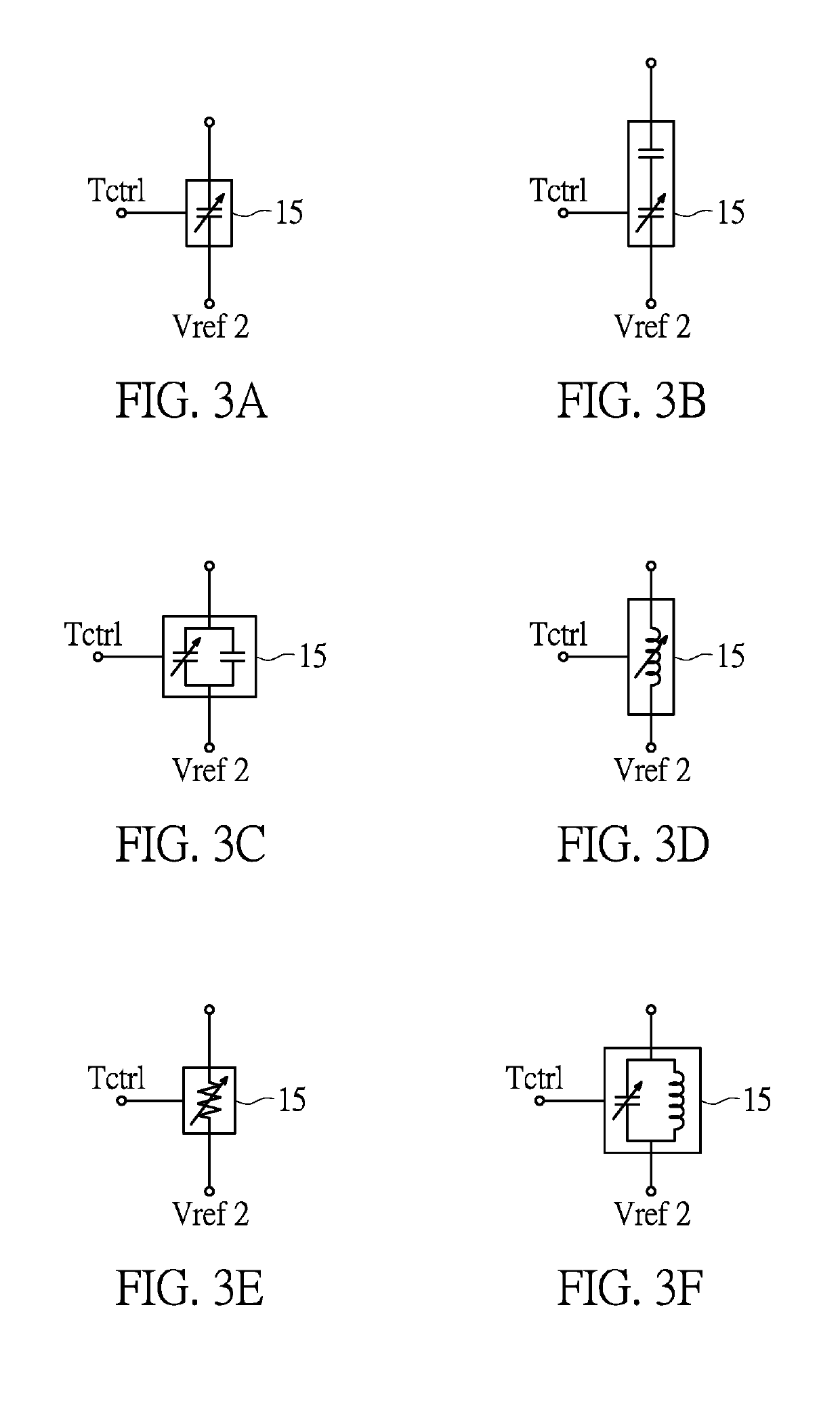
[0016]Reference is made to FIG. 1, FIG. 2 and FIGS. 3A-3Y, where FIG. 1 shows a diagram of an amplifier device according to an embodiment of the present disclosure, FIG. 2 shows a diagram of a first adjusting module and a second adjusting module according to an embodiment of the present disclosure, and FIGS. 3A-3Y show diagrams of an impedance unit implemented by different elements according to the embodiments of the present disclosure.

[0017]In the following description, for the sake of brevity, for elements with two ends in FIG. 1 and FIG. 2, the upper end would be the first end and the lower end would be the second end if an element is placed vertically, and the left end would be the...


PUM


Abstract

An amplifier device includes an amplifying unit, a bias module and an impedance unit. A first end of the amplifying unit electronically connects to a voltage source. A second end of the amplifying unit receives an input signal. The first end of the amplifying unit outputs an output signal amplified by the amplifying unit. A third end of the amplifying unit connects to a first reference potential. The bias module electrically connects to the second end of the amplifying unit for providing a bias voltage to the amplifying unit. An impedance unit is electrically connects to the bias module. An impedance value of the impedance unit is variable. The bias module adjusts the amplifier's linearity according to a frequency value of the input signal, a voltage value of the voltage source or a temperature value of the amplifier device. The impedance is adjusted according to the above-mentioned values.

Description

CROSS-REFERENCE TO RELATED APPLICATION[0001]This application claims priority of Taiwan application No. 105144234, which was filed on Dec. 30, 2016, and is included herein by reference.TECHNICAL FIELD[0002]The present disclosure relates to an amplifier device; in particular, to an amplifier device capable of improving linearity.BACKGROUND[0003]With the prevalence of mobile devices nowadays, amplifier devices are used in communication modules in great quantity. Due to the fact that the power-gain curve and power-phase curve of an amplifier device tend to be non-linear when they reach a certain level, amplifier devices are limited in power usage. Though the approaches of reducing the power or introducing a pre-distortion circuit may be utilized, the complexity of circuit design and cost would increase correspondingly. Moreover, the linearity of an amplifier device varies according to the input signal, voltage source or temperature, so that if a pre-distortion circuit is utilized as pre...

Claims


Application Information

Patent Timeline
Patent Type & Authority Patents(United States)
IPC IPC(8): H03F1/02H03F1/56H03F3/21H03F3/19
CPCH03F1/0216H03F1/56H03F3/19H03F3/21H03F2200/294H03F2200/451H03F2200/555H03F1/30H03F1/32H03F3/213H03F3/68H03F1/0261H03F1/302H03F3/193H03F3/45183H03F3/45475H03F2200/18
Inventor CHEN, CHIH-SHENGLO, HONG-JIA
Owner RICHWAVE TECH CORP
Learn More