
Method and apparatus for making an interconnection between power and signal cables

a technology of power and signal cables, applied in the direction of coupling devices, coupling devices engaging/disengaging, coupling device connections, etc., can solve the problems of coaxial cable size and interconnection becoming an impediment to system miniaturization

Active Publication Date: 2016-08-04
THE PHOENIX OF CHICAGO
View PDF9 Cites 8 Cited by
  • Summary
  • Abstract
  • Description
  • Claims
  • Application Information

AI Technical Summary

Benefits of technology

The present invention provides an interconnection for power and signal cables, including RF signals, with a connector plug bushing that can be securely attached to a mid- or backplane board using a clamp. The connector plug bushing has a resilient outwardly extending tab that provides a friction fit against the edge of the board opening to hold the bushing within the opening. The connector plug bushing can be easily inserted into the inner opening of the connector plug bushing until the flange on the male or female connector plug housing contacts the bushing body. The technical effects of this invention include improved reliability and durability of the interconnection, as well as simplified installation and maintenance.

Problems solved by technology

Additionally, as underlying electronic components of circuit packs become smaller, the size of coaxial cables and their interconnection may become an impediment to miniaturization of the system.

Method used


Image

  • Method and apparatus for making an interconnection between power and signal cables
  • Method and apparatus for making an interconnection between power and signal cables
  • Method and apparatus for making an interconnection between power and signal cables

Examples


Embodiment Construction

)

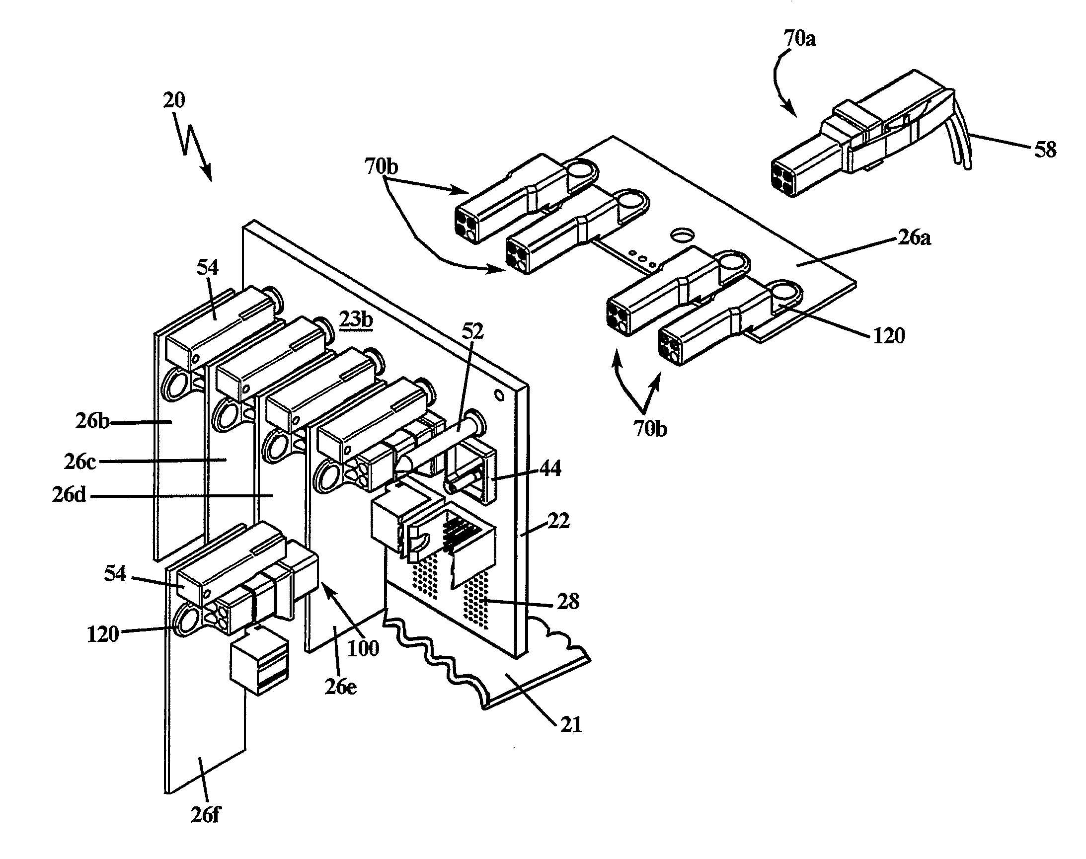
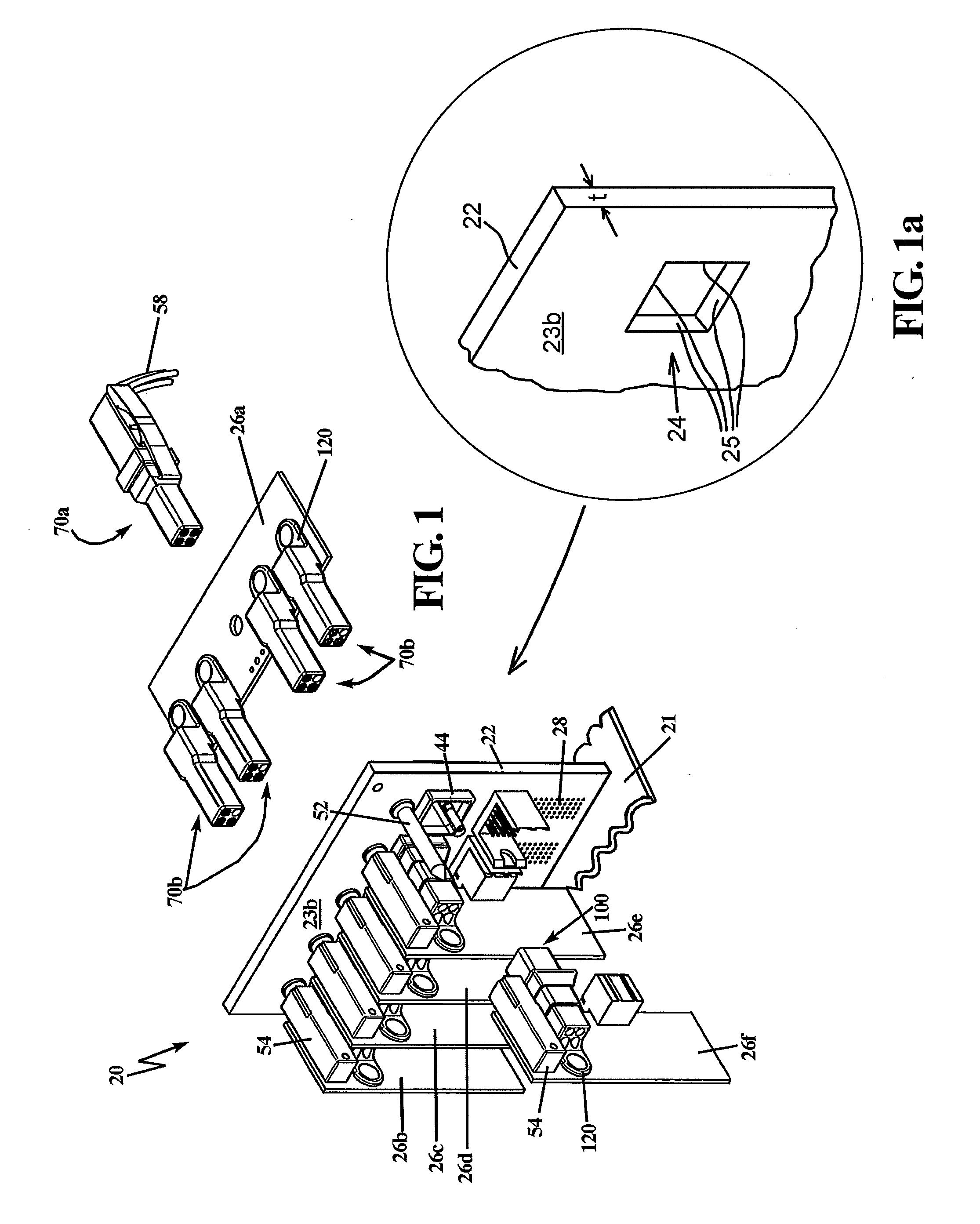
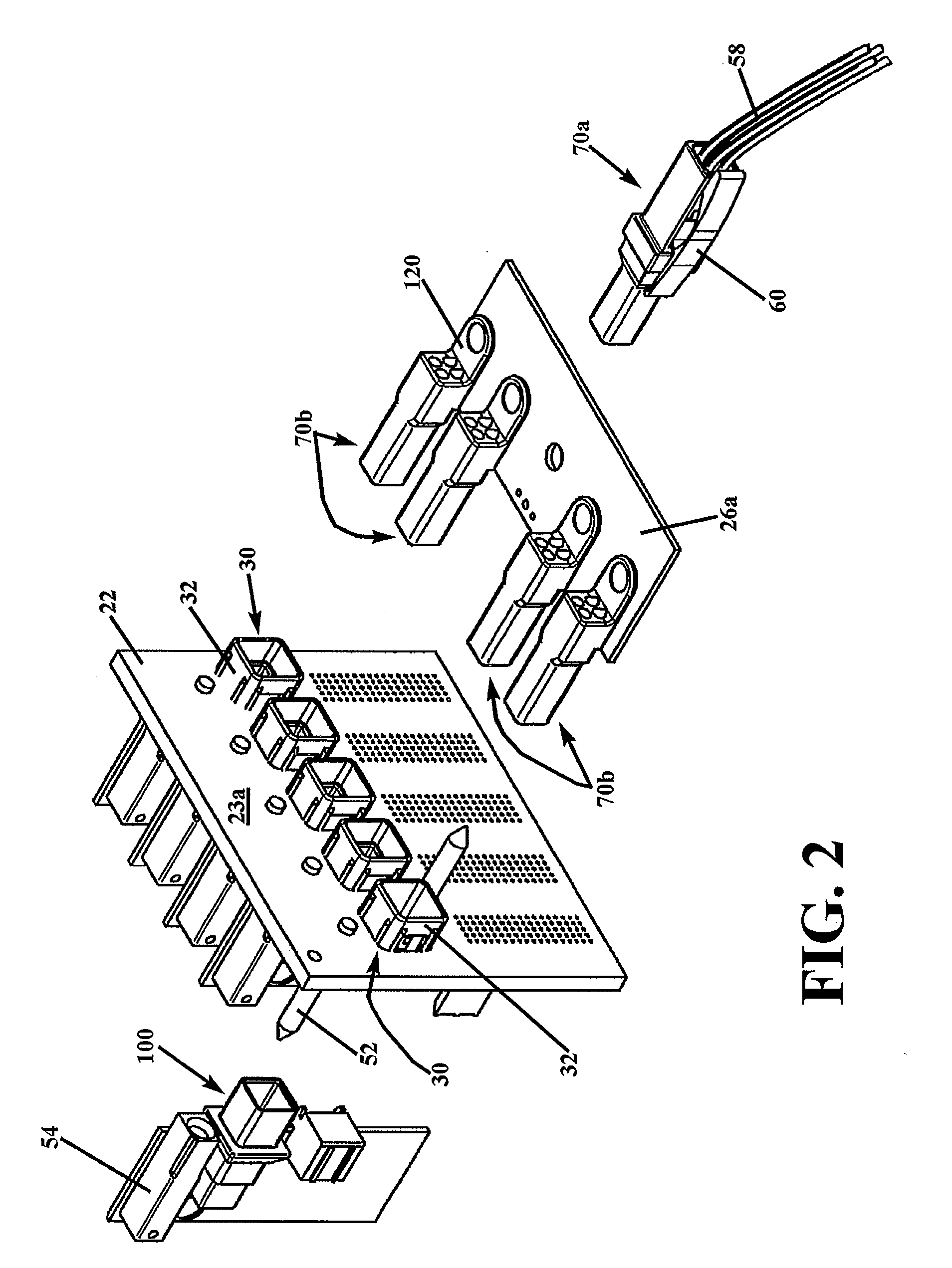
[0053]In describing the preferred embodiment of the present invention, reference will be made herein to FIGS. 1-30 of the drawings in which like numerals refer to like features of the invention.

[0054]The present invention provides a method, system and apparatus for making an interconnection between power cables and signal cables, and is particularly useful for boards connecting coaxial cables for RF signals in excess of 16 GHz frequency, for example, in the range of, but not limited to, 16 GHz to 40 GHz. Electrical and electronic devices have need for internal interconnection of such power and signal cables, often using a generally planar mid- or backplane board 22 as seen in FIGS. 1 and 2 mounted vertically on the cage or other structure 21 of the device. These boards may have one, two or more openings through board 22, such as the five openings as shown in which connector plug bushings 30 are inserted. The openings may be of any relative orientation, and may be horizontally and / o...


PUM


Abstract

A method, system and apparatus for making an interconnection between power cables and signal cables. A single electrical interface in mid- or backplane applications is introduced to accommodate a wide range of board thickness variations while maintaining a desired interface relationship, using a connector plug bushing, a male connector having a sliding fit with the bushing, a first coaxial connector plug, a female connector plug with a housing width sized to provide a sliding fit within the connector plug bushing inner opening, and a second coaxial connector plug in the free end of the female connector plug for connection to the power and signal cables. A constant impedance connector is used with the interconnection of the RF signal and power cables.

Description

BACKGROUND OF THE INVENTION[0001]1. Field of the Invention[0002]The present invention relates to a method, system and apparatus for making an interconnection for power cables and signal cables, particularly coaxial cables for RF signals operating in the range of, but not limited to, 16 GHz to 40 GHz.[0003]2. Description of Related Art[0004]Many electronic applications require extensive radio frequency (RF) cabling. For example a typical RF section on the backplane of an electronic interconnect device may consist of a large number of coaxial cable connections, as well as power cable connections.[0005]Additionally, as underlying electronic components of circuit packs become smaller, the size of coaxial cables and their interconnection may become an impediment to miniaturization of the system.[0006]It should be noted that the above concerns with the use of coaxial cables in a RF distribution fabric are present in many applications that require the use of numerous power and signal cable...

Claims


Application Information

Patent Timeline
IPC IPC(8): H01R24/52
CPCH01R24/52H01R43/26H01R24/60H01R2107/00
Inventor BRADLEY, ROBERT M.BALISTRERI, JAMES R.MATURO, JOHN E.
Owner THE PHOENIX OF CHICAGO
Learn More