Sound Generator

a generator and sound technology, applied in the direction of circuit lead arrangement/relief, electric transducer, electrical apparatus, etc., can solve the problem of comparatively difficult to fix the wire at the correct position properly

Inactive Publication Date: 2016-08-04
AAC TECH PTE LTD
View PDF3 Cites 3 Cited by
  • Summary
  • Abstract
  • Description
  • Claims
  • Application Information

AI Technical Summary

Problems solved by technology

In addition, because the wire is straight and bonded on the side of the frame, two parts are substanti

Method used


Image

  • Sound Generator
  • Sound Generator
  • Sound Generator

Examples


Embodiment Construction

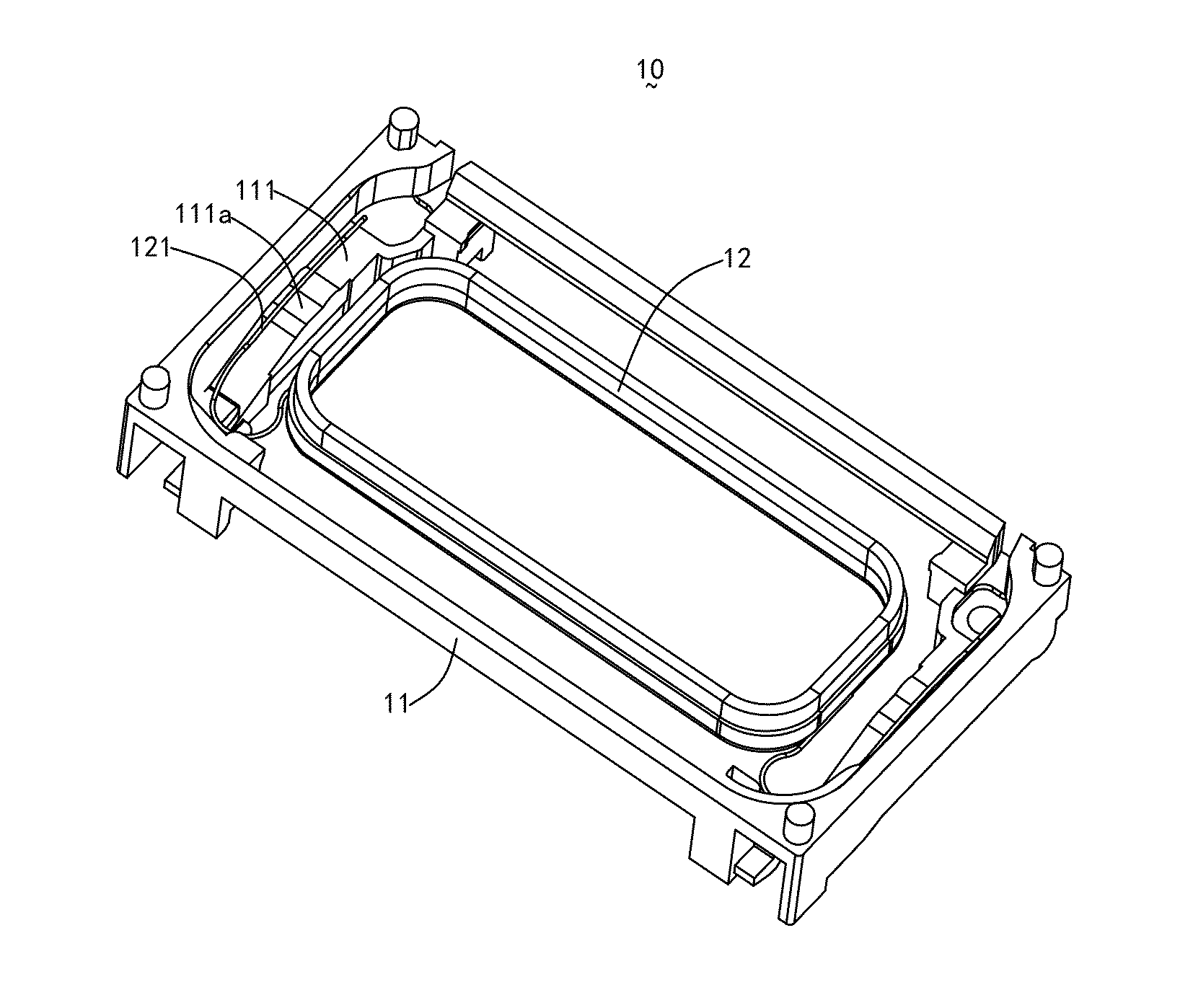
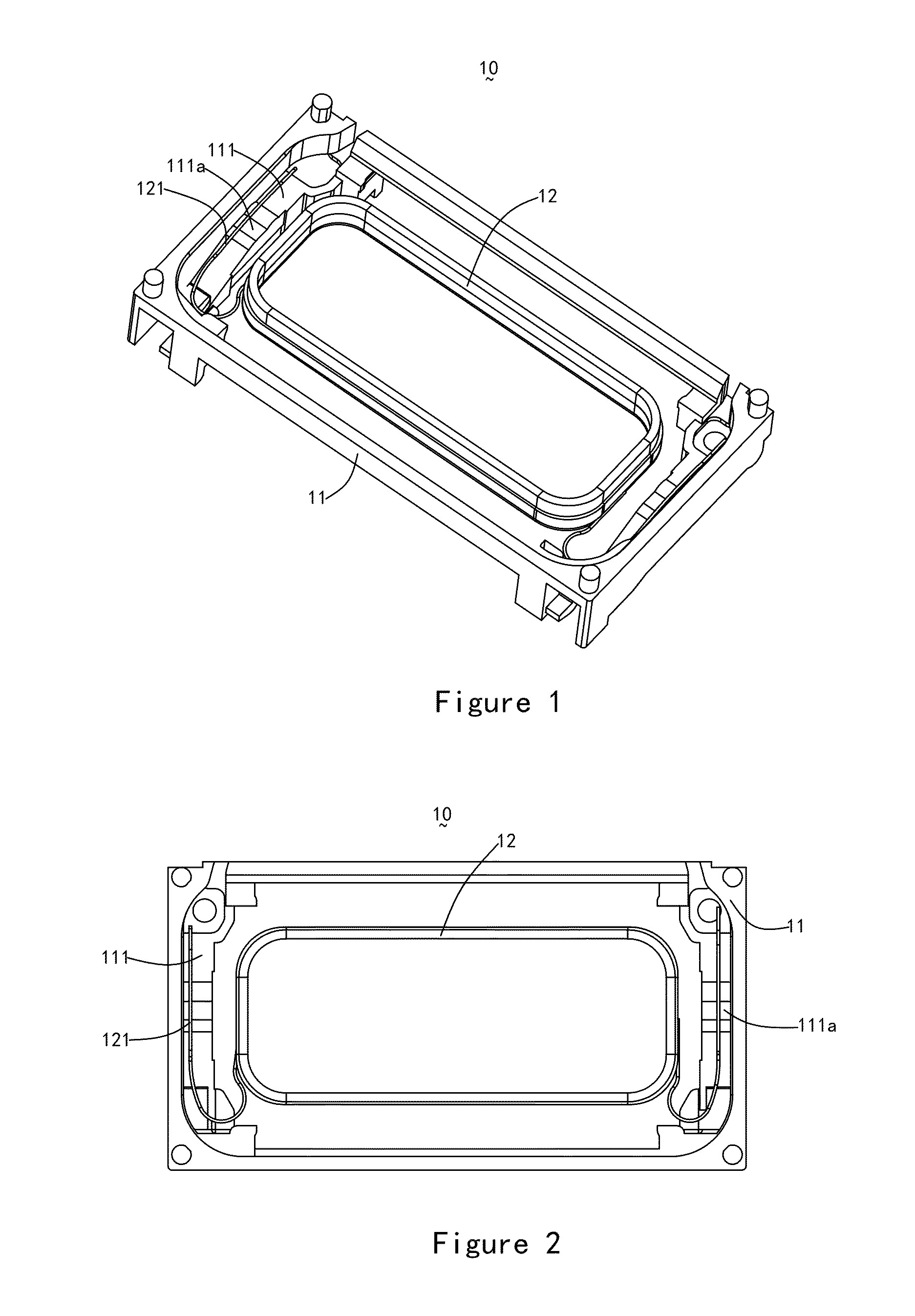
[0013]The present invention will hereinafter be described in detail with reference to an exemplary embodiment. To make the technical problems to be solved, technical solutions and beneficial effects of present disclosure more apparent, the present disclosure is described in further detail together with the figures and the embodiment. It should be understood the specific embodiment described hereby is only to explain this disclosure, not intended to limit this disclosure.

[0014]As shown in FIGS. 1 and 2, the sound generator 10 includes a frame 11 and a voice coil 12 connected with the frame 11. The frame 11 is a component for fixing the parts of the sound generator and is made of typically plastic. It may be a part made of the mixture of plastic and other material, such as the injection molding part composed of plastic and metallic material or other kind of assembly. The voice coil 12 is made of metal wire coils and is one of the important components of the sound generator. When an al...


PUM


Abstract

A sounder generator is disclosed. The sound generator includes a frame including a side wall forming a storage space; a voice coil connected with the frame and accommodated in the storage space, the voice coil including a coil body and a coil lead extending from coil body. The coil lead includes a fixed portion connected to the coil body; an arc portion extending from the fixed portion and convex toward the coil body; and a connecting portion extending from the arc portion and connected with the sidewall.

Description

FIELD OF THE INVENTION[0001]The present invention relates to a sound generator for converting electrical signals into sound waves, more particularly to a miniature sound generator.DESCRIPTION OF RELATED ART[0002]In the mobile Internet era, the number of smart mobile devices is on the rise. Among many mobile devices, mobile phone is undoubtedly the most common and most portable mobile terminal device. Currently, mobile phone's functions are much diversified; one of them is high-quality music feature. The speaker of the mobile phone is prerequisite to realize the high quality music feature. The mobile phones on the market at present adopt generally the miniature electromagnetic speaker for music playing.[0003]The sound generator includes normally a frame serving as a housing, a magnetic system fixed in the frame, and a vibration system which interacts with the magnetic system for producing vibrations. The magnetic system typically includes a yoke, a magnet fixed at a center of the yok...

Claims


Application Information

Patent Timeline
IPC IPC(8): H04R1/06H04R9/06
CPCH04R1/06H04R2499/11H04R9/06H04R9/046
Inventor WANG, CHANGLIANG
Owner AAC TECH PTE LTD
Why Eureka
Try Eureka