Acoustic Device

a technology of acoustic devices and speakers, which is applied in the direction of transducer details, electrical transducers, electrical apparatus, etc., can solve the problem of distortion of the sound generated by the speaker box

Active Publication Date: 2016-08-04
AAC TECH PTE LTD
View PDF10 Cites 10 Cited by
  • Summary
  • Abstract
  • Description
  • Claims
  • Application Information

AI Technical Summary

Problems solved by technology

Thus, an unbalance vibration occurred while the voice coil vibrating, which results in a di...

Method used


Image

  • Acoustic Device
  • Acoustic Device
  • Acoustic Device

Examples


Embodiment Construction

[0010]Reference will now be made to describe an exemplary embodiment of the present invention in detail. In this section we shall explain several exemplary embodiments of this invention with reference to the appended drawings. Whenever the shapes, relative positions and other aspects of the parts described in the embodiment are not clearly defined, the scope of the invention is not limited only to the parts shown, which are meant merely for the purpose of illustration. Also, while numerous details are set forth, it is understood that some embodiments of the invention may be practiced without these details. In other instances, well-known structures and techniques have not been shown in detail so as not to obscure the understanding of this description.

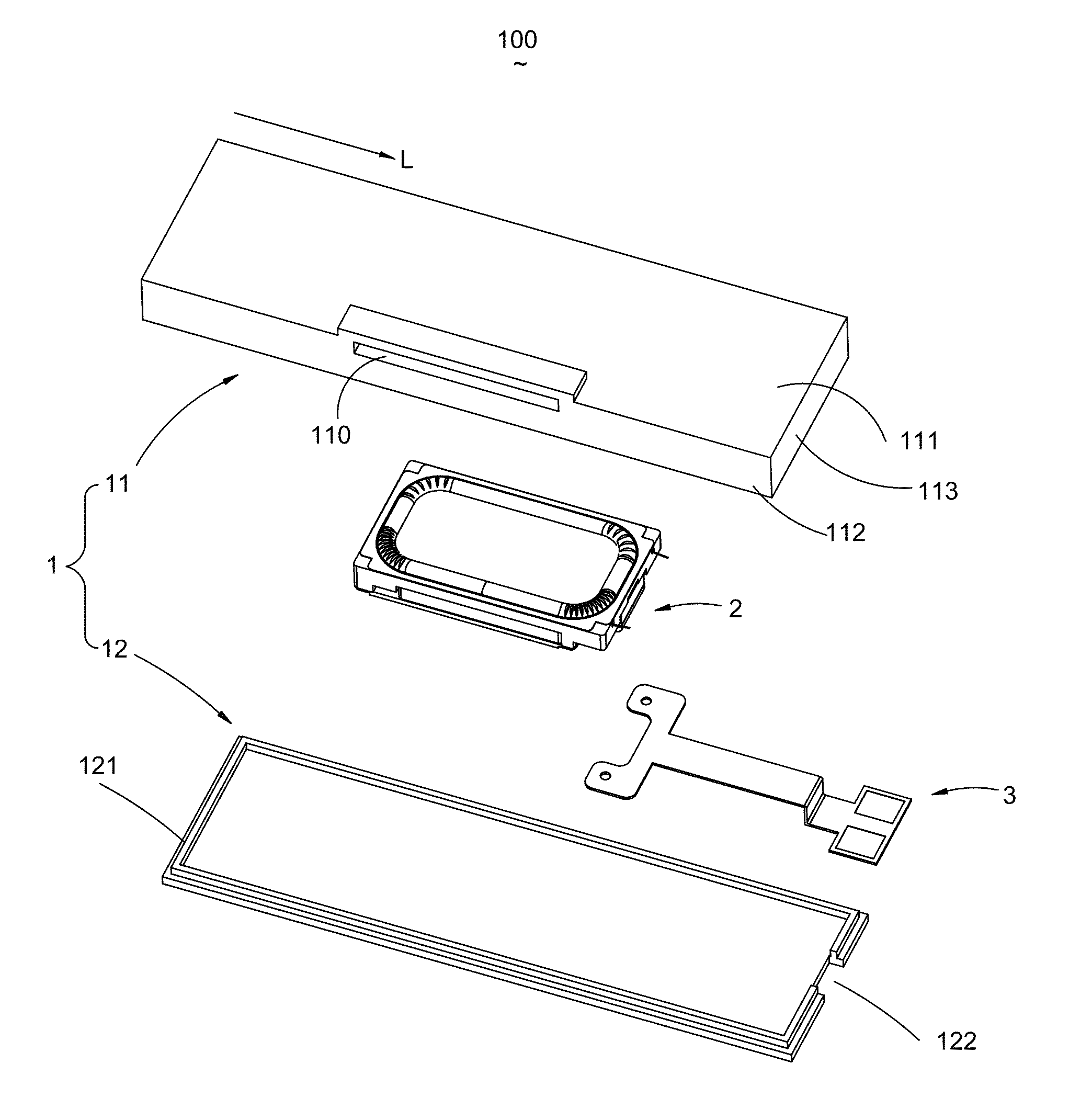
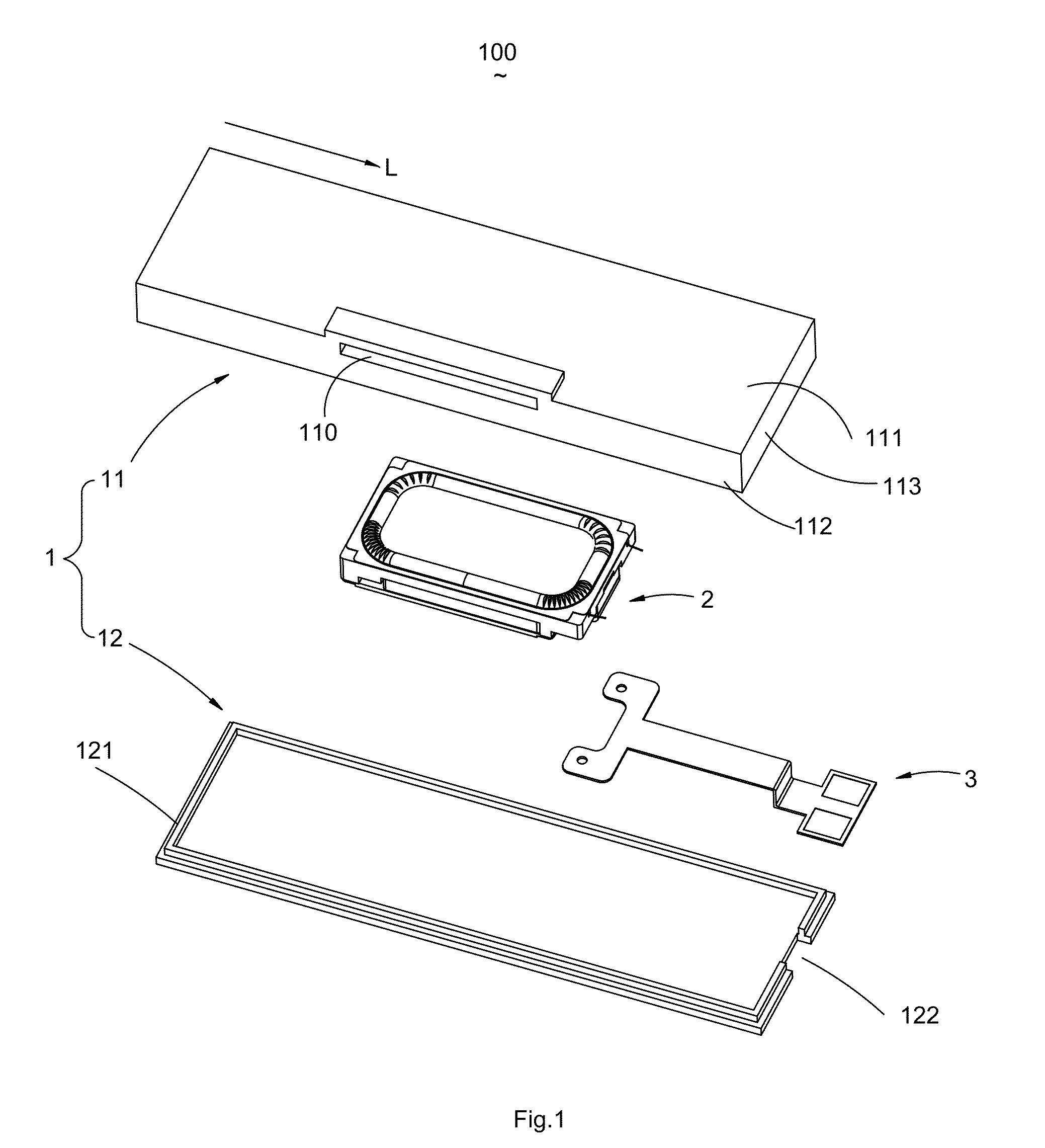
[0011]Referring to FIG. 1 and FIG. 2, an acoustic device 100 according to an exemplary embodiment includes a housing 1 having a cover 11 and a mounting plate 12 assembled with the cover 11 for forming a receiving space 10, a speaker unit...


PUM


Abstract

One embodiment of the invention discloses an acoustic device having a housing having an accommodating space with a sound hole formed thereon and communicating with the accommodating space; a speaker unit received in the accommodating space having a diaphragm including a first area away from the sound hole and a second area close to the through window; wherein, the diaphragm has a plurality of corrugations formed on the first area and the second area, respectively, and the amount of the corrugations on the first area is less than that on the second area.

Description

FIELD OF THE INVENTION[0001]One embodiment of the invention is related to an acoustic device, and more particularly to a speaker box with high audio performance.DESCRIPTION OF RELATED ART[0002]In modern consumer electronics, audio capability is playing an increasingly larger role as improvements in digital audio signal processing and audio content delivery continue to happen. There is a range of consumer electronics devices that are not dedicated or specialized audio playback devices, yet can benefit from improved audio performance. For instance, smart phones are ubiquitous.[0003]In a typical acoustic device, such as a speaker or a speaker box, a sound radiation surface is provided for generating sound. Generally, the sound radiation surface is a membrane or a diaphragm which is activated by an electrified voice coil. While activated, the sound radiation surface vibrates and produces audible sounds. Recently, the speaker box often defines a sound hole on the sidewall of the speaker ...

Claims


Application Information

Patent Timeline
IPC IPC(8): H04R1/28H04R9/06H04R1/02H04R7/14
CPCH04R1/2888H04R1/021H04R9/06H04R7/14H04R1/025
Inventor CAI, BINXU, YUNXIA
Owner AAC TECH PTE LTD
Why Eureka
Try Eureka