Hybrid Power Supply Unit For Audio Amplifier

a hybrid power supply and audio amplifier technology, applied in the direction of emergency power supply arrangements, low frequency amplifiers, transportation and packaging, etc., can solve the problems of low power supply average power level, poor suitability of power supply of existing art, cost and efficiency, etc., to reduce the physical size of the audio amplifier, reduce the size of the power supply unit, and high energy density of the battery stack

Inactive Publication Date: 2016-10-06
ZIMNICKI CHARLES +1
View PDF8 Cites 7 Cited by
  • Summary
  • Abstract
  • Description
  • Claims
  • Application Information

AI Technical Summary

Benefits of technology

[0037]Still a further advantage of the present disclosure is a reduction of the physical size of the audio amplifier because of the high energy density of the battery stack of the power supply unit.
[0038]Yet another advantage of the present disclosure is further reduction in size in the power supply unit because the main power supply is scaled to audio power averaged over seconds / minutes as opposed to milliseconds as with the present art.
[0039]Another advantage of the present disclosure is increased audio performance due to decreased audio noise—resulting from the reduction of the main power supply (with noise being proportional to the size of the power supply).
[0040]Yet another advantage of the present disclosure is providing increased power efficiency because the main power supply “sees” a constant load. Batteries (a high capacity energy “tank”) perform the job of load averaging, so the load appears nearly constant to the power supply. In other words, the batteries equalize power demand.
[0041]A further advantage of the present disclosure is increased power efficiency due to the fact that power supply is smaller. Audio power averaged over seconds / minutes is much lower than peak power. Power supplies generally exhibit somewhat constant efficiency, for example 90% —the 10% being lost to heat. A larger power supply will generally have higher losses for the same efficiency.
[0042]Finally, another advantage of the present disclosure is the reduction in heat production because the power supply unit is better sized for the load and can operate in its “greenest” mode.

Problems solved by technology

Generally, a longer time constant energy storage mechanism would result in “better” averaging, resulting in lower average power level required of the power supply.
Because instantaneous and short-time-scale average power demands of audio are orders of magnitude greater than the average power consumed over long timescales: power supplies of the existing art are poorly suited for the twin tasks of providing high quality audio and responding to a world that is increasingly concerned about power utilization and device efficiency.
A first known approach will be called the “brute force solution,” which can be effective but it is costly and inefficient.
P=22 A*80V=1760 W. Furthermore, there is an energy loss penalty to be paid.
Even if the power supply was 90% efficient, the loss would translate to roughly 176 W of power, which would be comparable to the 250 W power output of the amplifier (which in turn would make the total solution very inefficient).
Such solution would definitely not be considered environmentally friendly.
In addition, such an over-sized power supply would be much larger and heavier physically, making a solution potentially unattractive (both from the cost and aesthetics point of view).
Finally, the cost of “oversizing” the power supply by almost 10× makes it a poor solution for a product for a profit-driven company and customers that wish to be responsible consumers of energy.
However, the longer the decoupling network effective storage time, the more that can be gained in terms of power supply scaling.
Longer storage time results lower power requirements for the PSU (power supply unit) but still producing same quality music at the speaker.
Through some basic calculations, we can see that it would be difficult and costly to provide a capacitor bank sufficient for storing energy over a substantial amount of time.
Nevertheless, such solutions are still physically large.
It would be impractical to build decoupling networks to provide storage times longer than 50 mS, no matter how desirable—simply because of the physical volume of such a scaled solution would be large.

Method used


Image

  • Hybrid Power Supply Unit For Audio Amplifier
  • Hybrid Power Supply Unit For Audio Amplifier
  • Hybrid Power Supply Unit For Audio Amplifier

Examples


Embodiment Construction

[0060]Set forth below is a description of what is currently believed to be the preferred embodiment or best examples of the invention claimed. Future and present alternatives and modifications to this preferred embodiment are contemplated. Any alternatives or modifications which make insubstantial changes in function, in purpose, in structure or in result are intended to be covered by the claims in this patent.

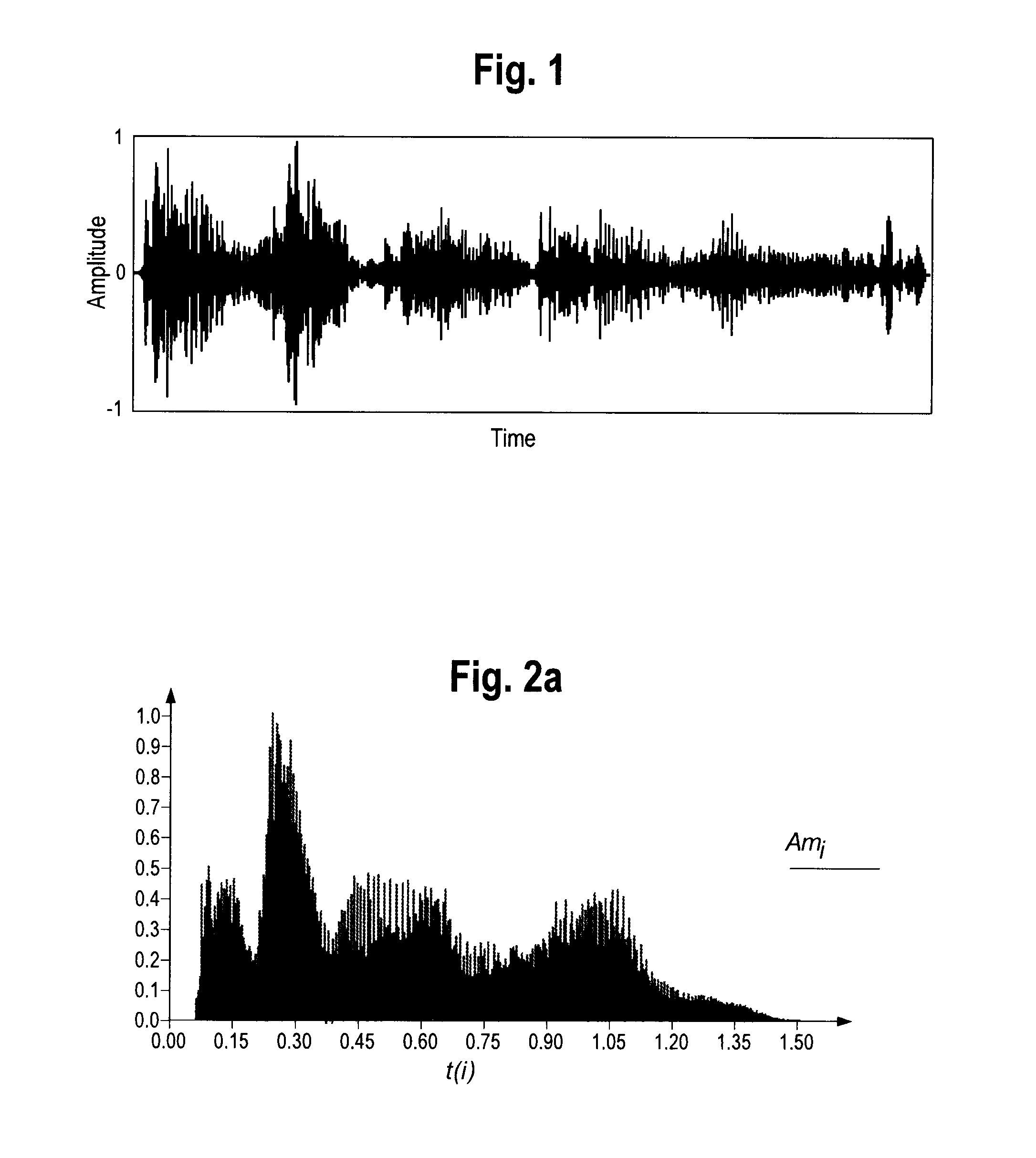
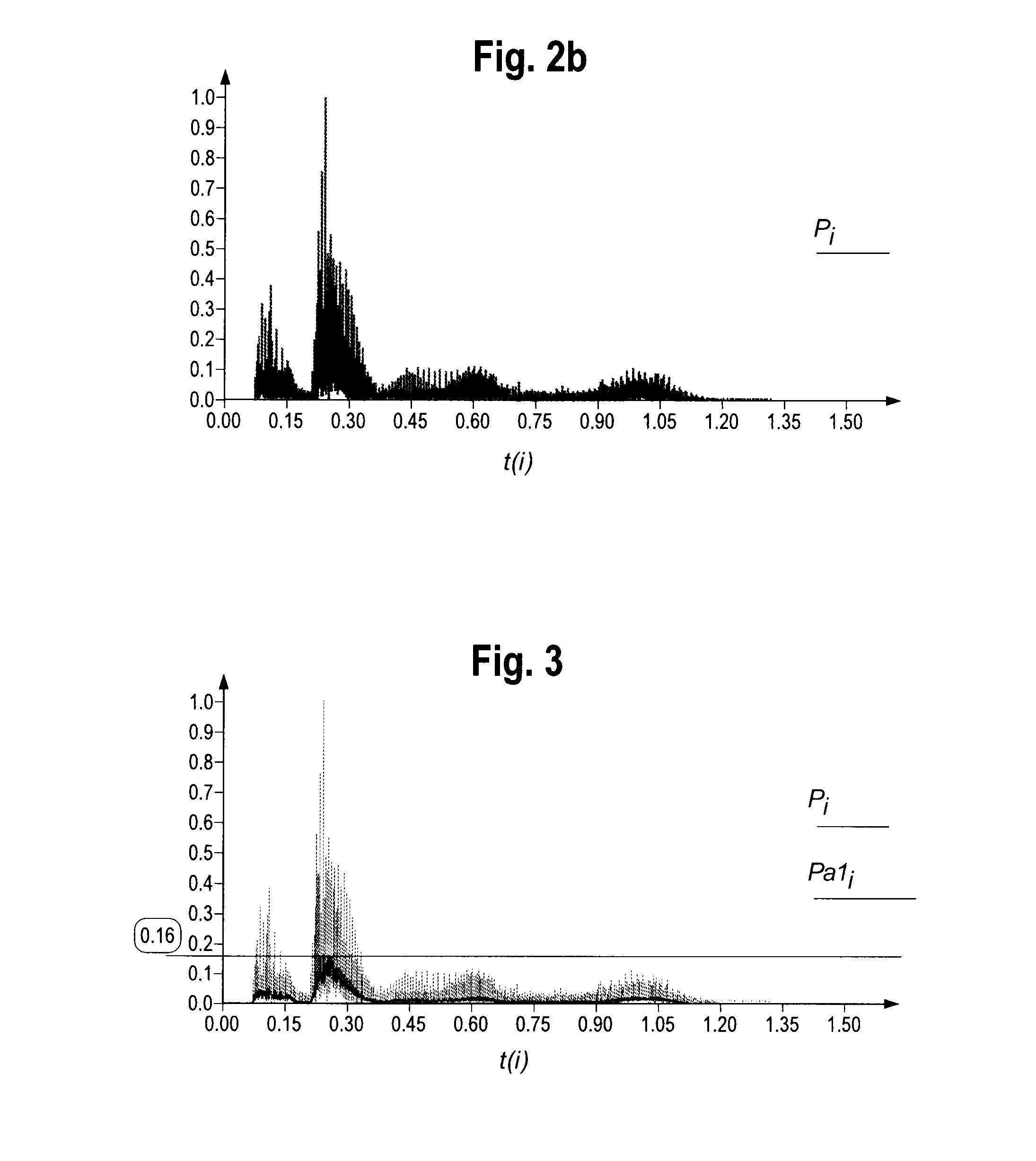
[0061]As seen in FIG. 1-5, the present disclosure involves a method and system for providing a hybrid power supply unit (i.e., battery plus main, plug-in power source) to an audio amplifier system. This process, as shown in FIG. 1, involves supporting a music signal, which appears as a complex and continuously varying AC waveform. As shown in FIG. 2a, the relative voltage amplitude of even a short (1.5 second) music sample can vary wildly. Accordingly, as shown in FIG. 2b, the relative audio power requirements for such a sample must vary even more dramatically, as the signal p...


PUM


Abstract

A system and method for using a circuit for providing power from multiple sources for a variable audio amplifier. The system includes a battery, a power supply and a controller which provides a power supply for the variable load demands of the amplifier, while still maintaining a substantially constant battery charge over an extended period of time.

Description

RELATED APPLICATION DATA[0001]This application claims priority to provisional patent application No. 61 / 975,249, filed on Apr. 4, 2014.FIELD OF THE DISCLOSURE[0002]The present disclosure relates to a system and method for the more efficient supply of power to an audio amplifier system. In particular, the present disclosure relates to the use of electrochemical energy storage units for instantaneously meeting peak power demands in an audio amplifier system.BACKGROUND[0003]Traditionally, in an audio amplifier, electrolytic capacitors are used for decoupling of the power supply from the rest of the amplifier's circuitry. High power audio amplifiers, and especially class-D amplifiers, are very different from an average electrical circuit because of the way they use power (as compared to, for instance, an electrical heater). The power needed for a high-efficiency Audio Amplifier is highly dependent upon the instantaneous power fed to the speakers. The highly inconsistent and “unpredictab...

Claims


Application Information

Patent Timeline
Patent Type & Authority Applications(United States)
IPC IPC(8): H02J7/00H02M7/04H02J9/06H03F3/185H03F3/217
CPCH02J7/0068H03F3/185H03F2200/03H02J9/061H02M7/04H03F3/2171H03F1/0211H03F3/2173H02J7/0016
Inventor ZIMNICKI, CHARLESRACZYNSKI, WALTER
Owner ZIMNICKI CHARLES
Why Eureka
Try Eureka