Eureka AIR delivers breakthrough ideas for toughest innovation challenges, trusted by R&D personnel around the world.

Method of manufacturing decorative molding

Active Publication Date: 2016-08-11
TOYODA GOSEI CO LTD
View PDF3 Cites 10 Cited by
  • Summary
  • Abstract
  • Description
  • Claims
  • Application Information

AI Technical Summary

Benefits of technology

The patent describes a rubber piece made from a fiat plate-like rubber that has a hardness of not more than 80 degrees and a thickness of not less than 3 mm. This allows the rubber piece to accommodate positional deviations in the area to be decorated, resulting in a reliable transfer. The hardness of the rubber piece can be measured using a procedure described in Japan Industrial Standard JIS K 6253. The technical effect of this invention is to provide a reliable and flexible tool for decorating areas that can tolerate positional deviation, while ensuring accurate and high-quality transfer of the decor.

Problems solved by technology

With such conventional hot stamping, forming a decorative layer in a large grille having a size exceeding 400 mm has been difficult.
Vehicle grilles having such shapes tend to suffer significant variability in shrinkage depending on conditions, such as dwell pressure and temperature during molding, thereby lowering dimensional accuracy.
This leads to a problem that the positions of surface sections to be decorated 5a and 5b are deviated, as illustrated in FIG. 12.
Since the rubber piece 24b is shaped to fit the surface section to be decorated 5b, such a misalignment causes difficulty in uniform contact (uniform pressing).
Such nonuniform pressure on the surface section to be decorated 5b results in a transfer defect.
The problem of deviated positions for decoration due to the low dimensional accuracy arises particularly in large components to be decorated with an area to be decorated having a size exceeding 400 mm.
Vehicle grilles in particular are large components and are susceptible to low dimensional accuracy.
To solve, such a problem, a hot stamping process may be performed more than once using a segmented stamping plate while e pressing positions are shifted plural times. This approach, however, is problematic in that the increased number of operation processes results in increased manufacturing costs.
The hot stamping method described in JP 2002-166700P which is directed to a plastic molding like an air conditioner grille, poses difficulty in application to a component, like a vehicle grille, having spaced-apart sections to be decorated (surface sections co be decorated) with gaps therebetween.
More specifically, the existence of multiple and spaced-apart surface sections to be decorated with gaps therebetween presents a problem as described above that the positions of the surface sections to be decorated relative to each other are deviated.
No solution is described for such problems in JP 2002-166700A, posing difficulty in the application of the technique described therein.
Additionally, the rubber piece will deteriorate and shrink (be fatigued) due to the reiteration of pressing.
In a conventional process where the pressing amount (a stroke) is controlled, the surface sections to be decorated cannot be pressed sufficiently with a fatigued and shrunk rubber piece.

Method used


Image

  • Method of manufacturing decorative molding
  • Method of manufacturing decorative molding
  • Method of manufacturing decorative molding

Examples


embodiment

Radiator Grille 1

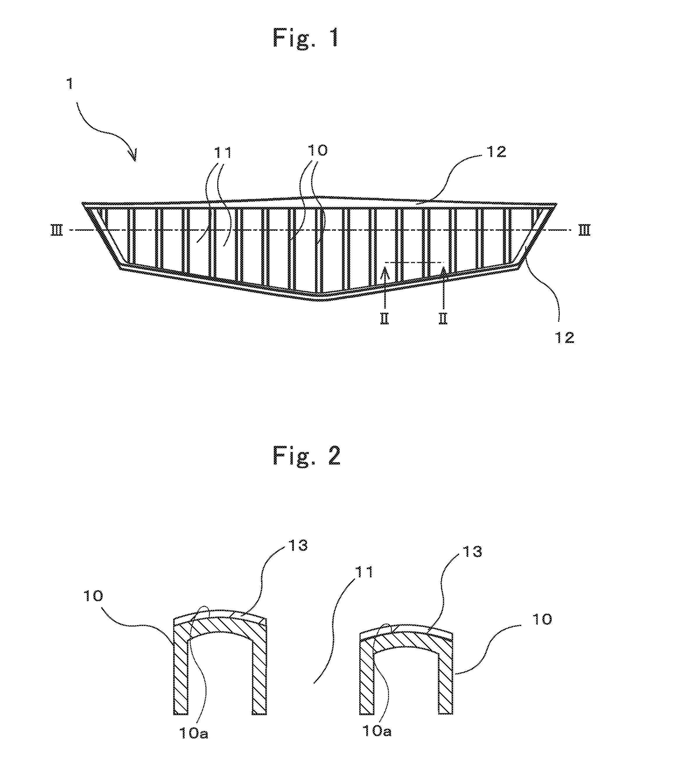
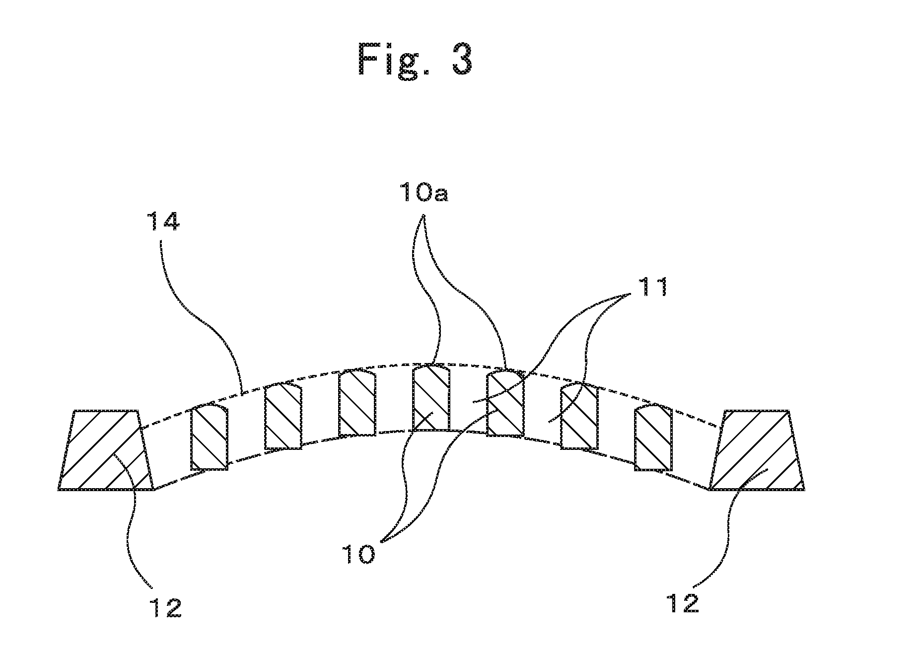
[0040]As illustrated in the front view in FIG. 1, the radiator grille 1 spreads in a vehicle width direction (in the lateral direction in FIG. 1) in shape. The grille 1 includes ridges 10 extending in a direction perpendicular to the vehicle width direction (in the vertical direction in FIG. 1) and arranged side by side in the vehicle width direction with gaps 11 therebetween. The grille 1 includes a perimeter portion 12 on the perimeter of the area in which the ridges 10 and the gaps 11 are placed. Each ridge 10 has ends in its extending direction, which are integrated with the perimeter portion 12.

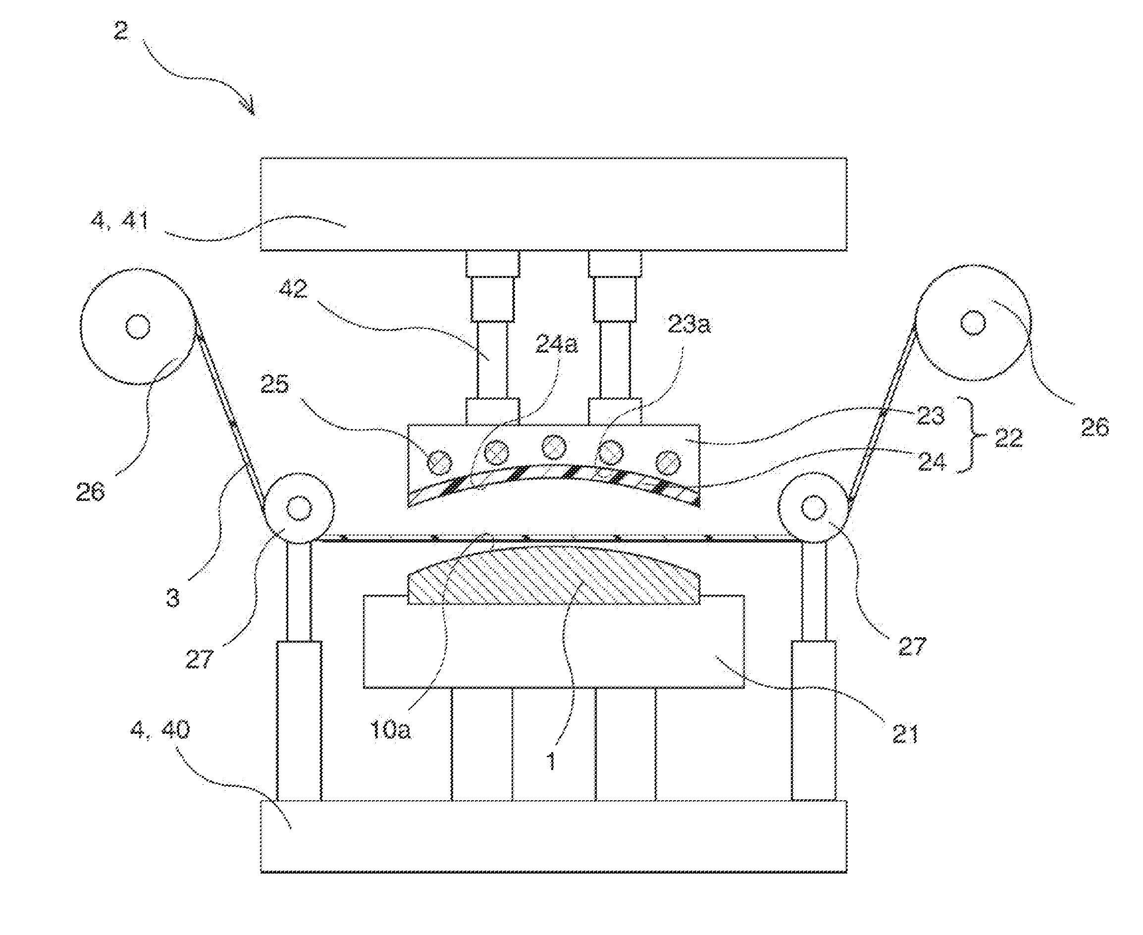
[0041]As illustrated in the sectional view in FIG. 2, each ridge 10 has a tapered and substantially inverted-U-shaped section having a projecting curved end surface 10a. FIG. 2 is a section along the line II-II in FIG. 1. In the embodiment, hot stamping is employed to thermal transfer a transfer sheet to the end surface 10a of each ridge 10 in the grille 1 to form a deco...


PUM

PropertyMeasurementUnit
Lengthaaaaaaaaaa
Angleaaaaaaaaaa
Lengthaaaaaaaaaa

Abstract

The present invention provides a method of manufacturing a decorative molding with a capability to decorate a large component to be decorated. The method includes pressing a heated pressing member against an area to be decorated having a plurality of spaced-apart surface sections to be decorated, with a transfer sheet interposed between the pressing member and the area to be decorated, to transfer decorative layers to the surface section to be decorated. The area to be decorated has a maximum width of not less than 400 mm. The pressing member has a pressing surface configured to come in contact with the transfer sheet and constituted by a rubber piece shaped into a flat plate. The rubber piece has a hardness of not more than 80 degrees and a thickness of not less than 3 mm, and is curved to fit a general surface shape of the area to be decorated.

Description

BACKGROUND[0001]1. Technical Field[0002]The present invention relates to a method of manufacturing a decorative molding, more particularly, to a method of manufacturing a large decorative molding having a plurality of spaced-apart surface sections to be decorated.[0003]2. Related Art[0004]Vehicles include a radiator grille, which is placed at the vehicle's front end and functions as an air inlet to supply air to the radiator behind the grille while traveling. To perform this function, radiator grilles are formed to have a louver or a mesh that has gaps serving as the air inlets. Additionally, radiator grilles, which are placed on the front surfaces (the outer periphery surfaces) of vehicles, are required to offer high designabilities. To meet such requirements, decorations are added to the front end (the tip) of a louver or a mesh.[0005]One way to decorate a radiator grille (a resin molding) is to form a decorative layer, by hot stamping, on a surface section to be decorated at the ...

Claims


Application Information

Patent Timeline
IPC IPC(8): B44C1/24B44C1/10B44C1/14
CPCB44C1/24B44C1/105B44C1/14B44C1/1712B29C66/81264B29C66/81423
Inventor KAJITANI, TAKUSHIIIMURA, KIMIHIROMIYAMOTO, SHOJIRO
Owner TOYODA GOSEI CO LTD
Why Eureka
Eureka Blog
Learn More