Vehicular air-conditioning unit

Inactive Publication Date: 2016-08-11
DENSO CORP
View PDF90 Cites 40 Cited by
  • Summary
  • Abstract
  • Description
  • Claims
  • Application Information

AI Technical Summary

Benefits of technology

[0010]As described above, in the second blowing mode, air introduced to the other end of the first ventilation passage from outside of the air-conditioning case flows to the one end of the second ventilation passage through the communication-ventilation passage after flowing from the other end to the one end of the first ventilation passage. The air flowing to the one end of the second ventilation passage flows from the one end of the second ventilation passage to the other end of the second ventilation passage and is blown from the other end of the second ventilation passage into the vehicle compartment. Accordingly, the air introduced into the air-conditioning case is blown into the vehicle compartment after flowing sequentially through the first heat exchanger and the second heat exchanger. Thus, an air temperature can be adjusted effectively by introducing air to pass through the heat exchanger twice in the air-conditioning case.
[0011]Moreover, in the first blowing mode, (i) air, which i

Problems solved by technology

Accordingly, there may be a possibility of being difficult to ventilate the conditioned air in a large volume.
Therefore, the passenger's comfort may be spo

Method used


Image

  • Vehicular air-conditioning unit
  • Vehicular air-conditioning unit
  • Vehicular air-conditioning unit

Examples


first embodiment

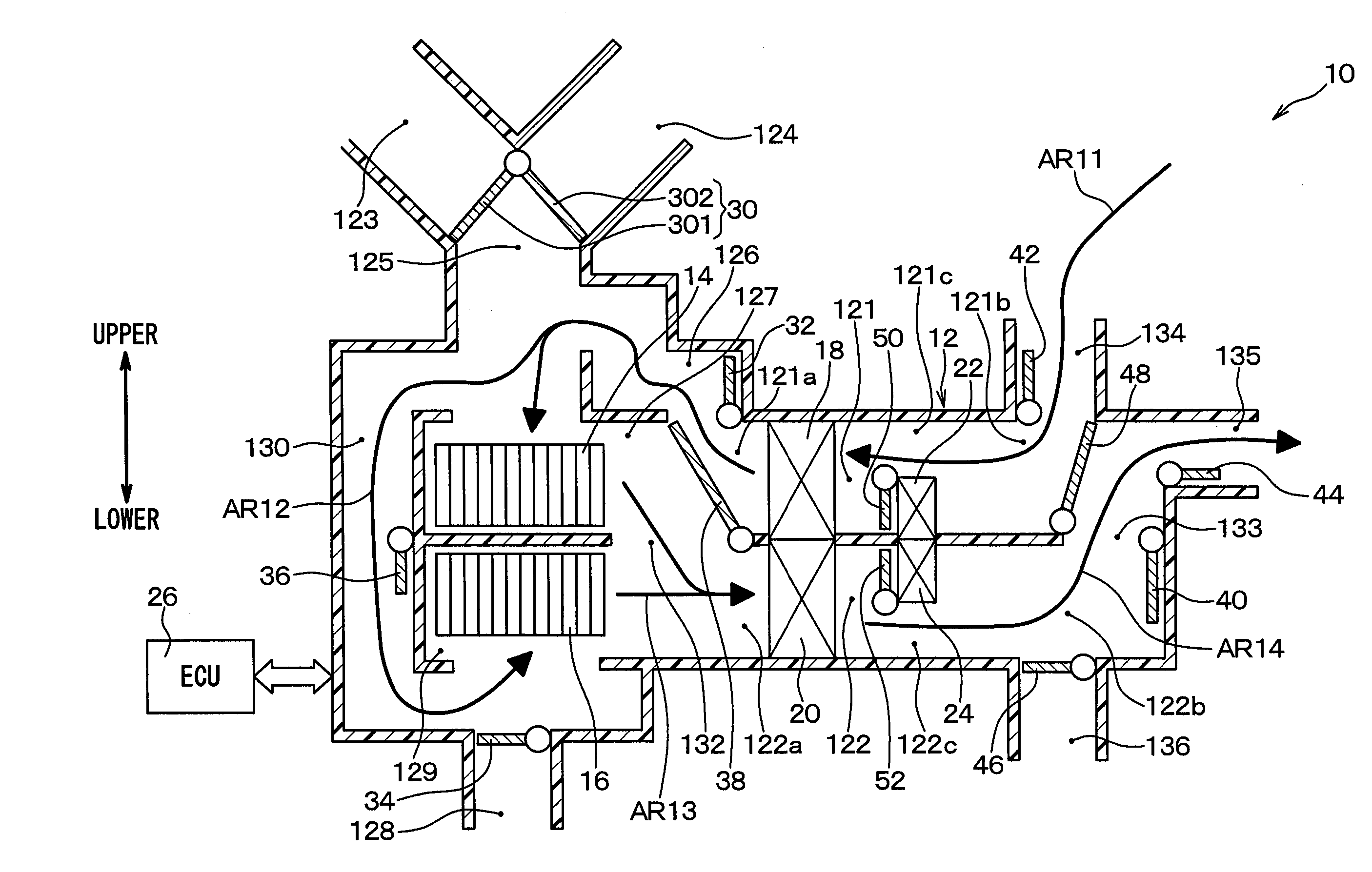
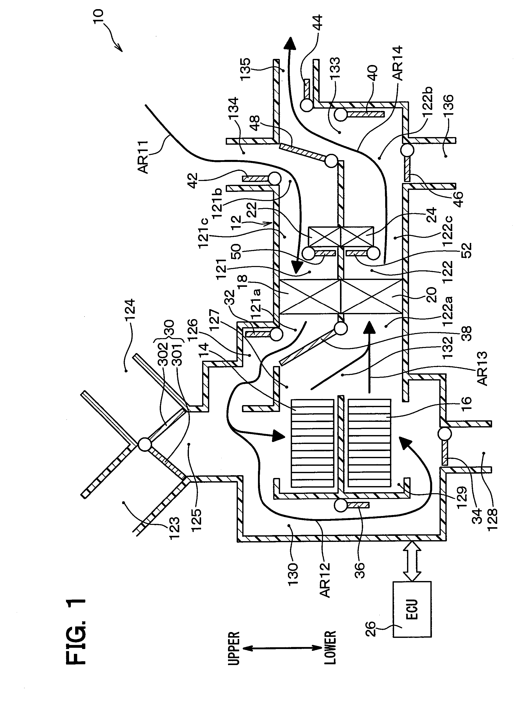
[0024]FIG. 1 is a schematic sectional view illustrating a vehicular air-conditioning unit 10 of the present embodiment. The vehicular air-conditioning unit 10 (referred to as an air-conditioning unit 10 hereafter) is disposed in a front area in a vehicle compartment. The air-conditioning unit 10 constitutes, for example, a part of an air conditioner for a vehicle provided with a refrigeration cycle that has a compressor and a condenser disposed in an engine room. An arrow showing an upper-lower direction in FIG. 1 shows an upper-lower direction on a condition where the air-conditioning unit 10 is disposed in the vehicle. Hereafter, a vehicle upper-lower direction that is the upper-lower direction on the condition of being disposed in the vehicle will be referred to as an upper-lower direction, and a direction perpendicular to the vehicle upper-lower direction will be referred to as a horizontal direction.

[0025]As shown in FIG. 1, the air-conditioning unit 10 has an air-conditioning ...

second embodiment

[0087]A second embodiment of the present disclosure will be described. In the present embodiment, features that are different from the first embodiment will be described mainly. Features corresponding to or equal to that of the preceding embodiment will be omitted or described simply. This is the same in the third embodiment and subsequent embodiments.

[0088]FIG. 4 is a sectional view schematically illustrating an air-conditioning unit 10 of the present embodiment. As shown in FIG. 4, the air-conditioning unit 10 of the present embodiment is different from the air-conditioning unit 10 of the first embodiment in a point of having no circular ventilation passage 126 (refer FIG. 1), the circular-ventilation-passage door 32, the second communication-ventilation passage 132, nor the second communication-ventilation-passage door 38.

[0089]Specifically, according to the air-conditioning unit 10 of the present embodiment, the ECU 26 sets an operation state of the air-conditioning unit 10 in t...

third embodiment

[0092]A third embodiment of the present disclosure will be described. In the present embodiment, features that are different from the first embodiment will be described mainly.

[0093]FIG. 5 is a sectional view schematically illustrating an air-conditioning unit 10 of the present embodiment. As shown in FIG. 5, the air-conditioning unit 10 of the present embodiment has no circular-ventilation-passage door 32 (refer FIG. 1), the first communication-ventilation-passage door 36, the first blower 14, the first-blower housing portion 127, the second inside-air introducing port 128, nor the second inside-air door 34. The air-conditioning unit 10 of the present embodiment has a circular ventilation passage 1261 shown in FIG. 5 instead of the circular ventilation passage 126 of the first embodiment, a second communication-ventilation passage 1321 shown in FIG. 5 instead of the second communication-ventilation passage 132 of the first embodiment, and a second communication-ventilation-passage ...


PUM


Abstract

A vehicular air-conditioning unit has an air-conditioning case, a first ventilation passage and a second ventilation passage, a first communication-ventilation passage defined in the air-conditioning case, the first communication-ventilation passage through which one end of the first ventilation passage communicates with one end of the second ventilation passage, a first heat exchanger that heats or cools air flowing in the first ventilation passage, a second heat exchanger that heats or cools air flowing in the second ventilation passage, and a blowing mode switching device setting any one of blowing modes. The blowing modes include (i) a first blowing mode in which air is blown into a vehicle compartment after flowing through the first ventilation passage and in which air is blown into the vehicle compartment after flowing through the second ventilation passage and (ii) a second blowing mode in which air flows into the second ventilation passage through the first communication-ventilation passage after flowing through the first ventilation passage and is blown into the vehicle compartment.

Description

CROSS REFERENCE TO RELATED APPLICATION[0001]This application is based on Japanese Patent Application No. 2013-193027 filed on Sep. 18, 2013, the disclosure of which is incorporated herein by reference.TECHNICAL FIELD[0002]The present disclosure relates to a vehicular air-conditioning unit having two ventilation passages arranged in parallel with each other.BACKGROUND ART[0003]A conventional technique regarding an air conditioner for a vehicle is disclosed in, for example, Patent Literature 1. An air conditioner for a vehicle disclosed in Patent Literature 1 has an air-conditioning case and an evaporator that is a heat exchanger and disposed in the air-conditioning case. A heat exchanging portion of the evaporator is divided into a first portion and a second portion. A conditioned air flowing in the air-conditioning case flows in the first portion of the evaporator, further flows in the second portion of the evaporator, and is blown into a vehicle compartment subsequently. Thus, by i...

Claims


Application Information

Patent Timeline
IPC IPC(8): B60H1/32B60H1/00
CPCB60H1/0005B60H2001/00107B60H2001/00135B60H2001/00092B60H2001/00085B60H1/00B60H1/00849B60H1/00842B60H1/00678B60H2001/00721B60H1/3227
Inventor MAEDA, KENICHIROKATO, SHINYA
Owner DENSO CORP
Why Eureka
Try Eureka