Manufacturing method of an attraction plate for electromagnetic door locks

Active Publication Date: 2016-09-01
LIAO YI FAN
View PDF5 Cites 1 Cited by
  • Summary
  • Abstract
  • Description
  • Claims
  • Application Information

AI Technical Summary

Benefits of technology

[0010]With structures disclosed above, the present invention has the arch design to increase a tensile value of the electric magnet for door locks instead of the conventional method of

Problems solved by technology

According to experiments conducted by the inventor, when Frolov's invention is applied to attraction plates with different thickness, the

Method used


Image

  • Manufacturing method of an attraction plate for electromagnetic door locks
  • Manufacturing method of an attraction plate for electromagnetic door locks
  • Manufacturing method of an attraction plate for electromagnetic door locks

Examples


Example

[0027]Referring to FIGS. 3-9, in a preferred embodiment, the present invention comprises the following steps.

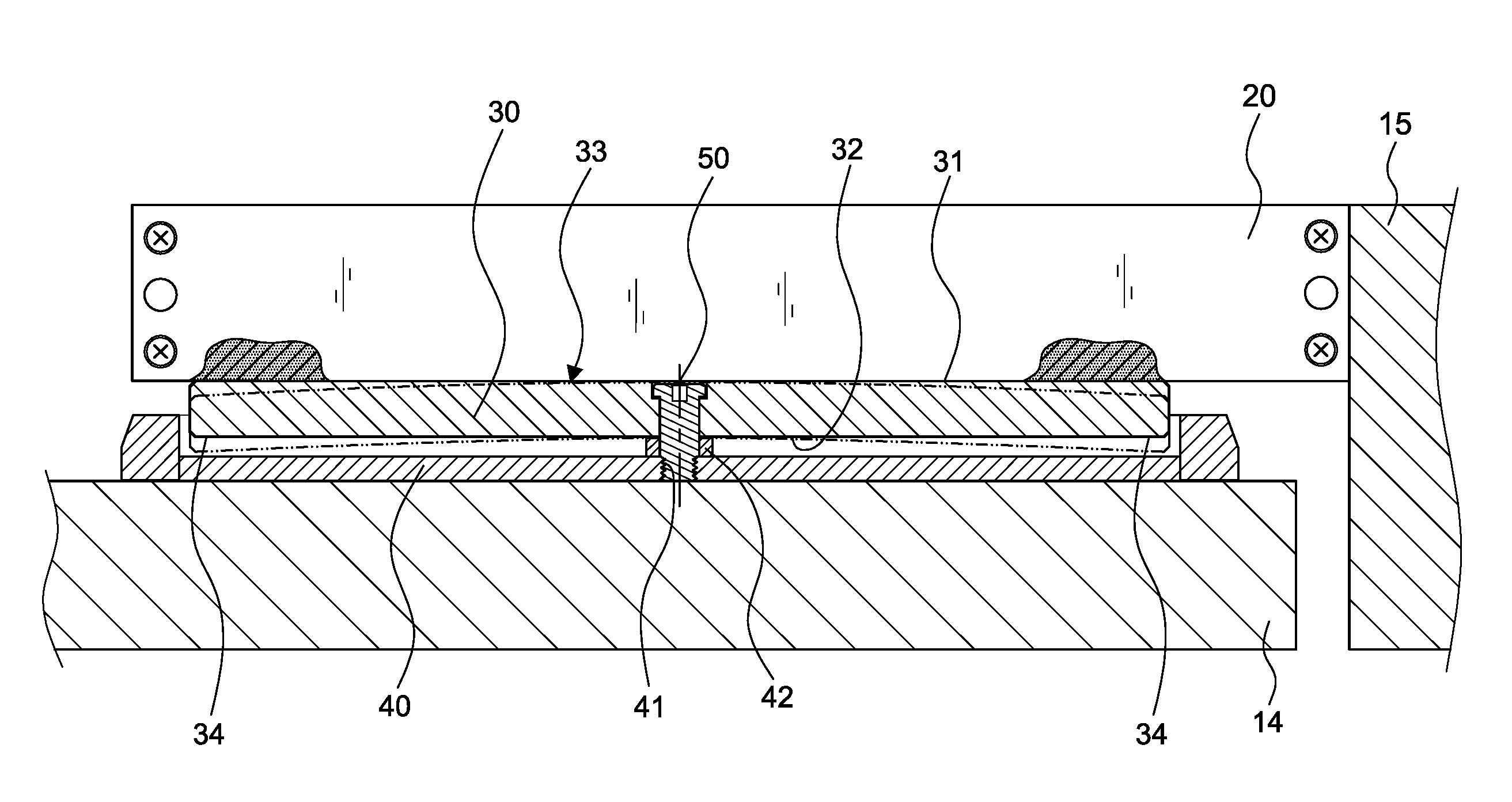
[0028]Step a: providing an electric magnet 20 in a long shape to be fixed to a door fame 15.

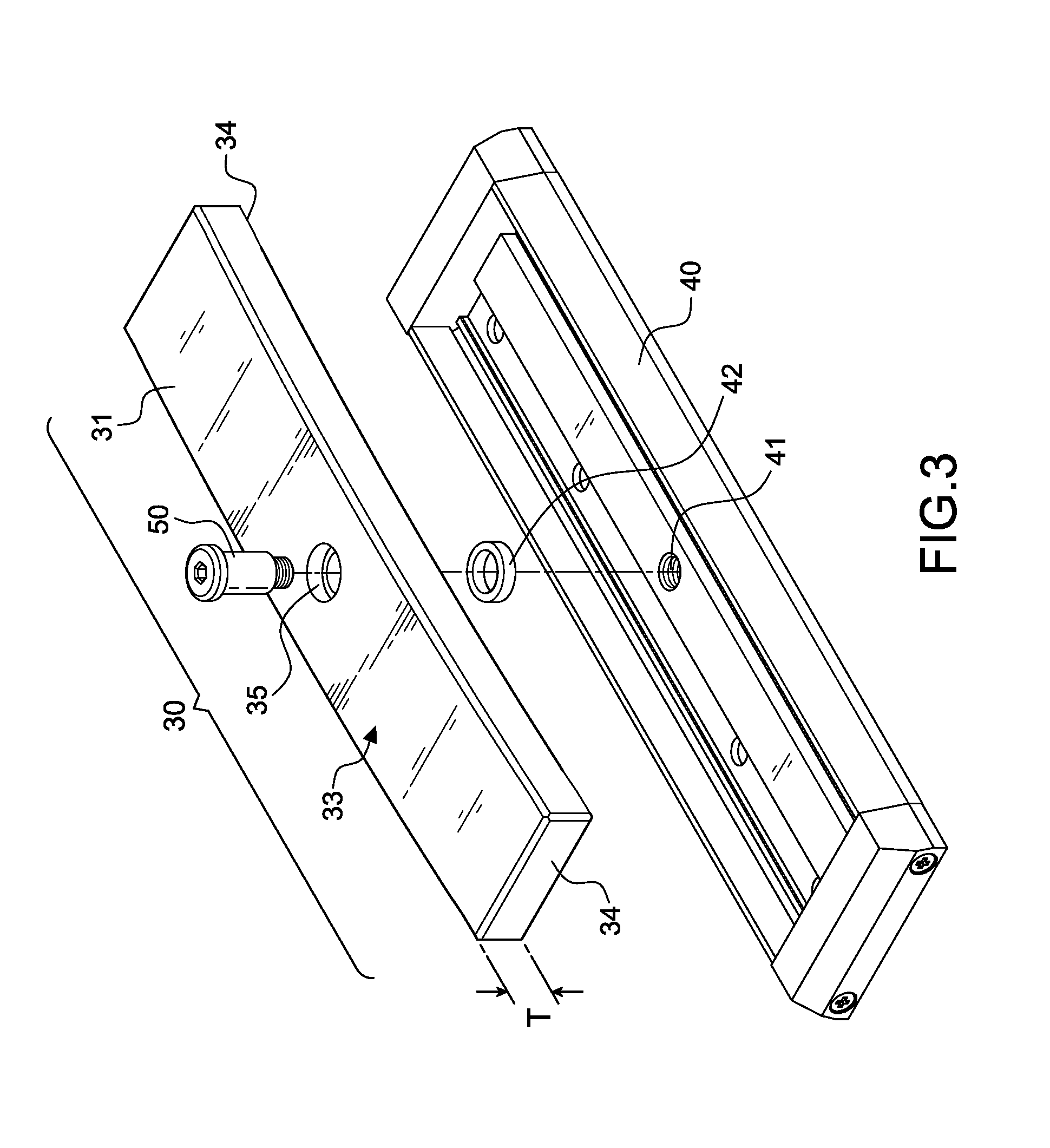
[0029]Step b: providing a mounted body 40 disposed at a corresponding side to the electric magnet 20 with a positioning hole 41 arranged in the middle thereof. The mounted body 40 can be in different design to be installed on a door plate 14. In this embodiment, it can be a box-shaped body, a U-shaped body, a L-shaped body, a flat body; or it can be made in one piece together with the door plate 14 for attraction engagement.

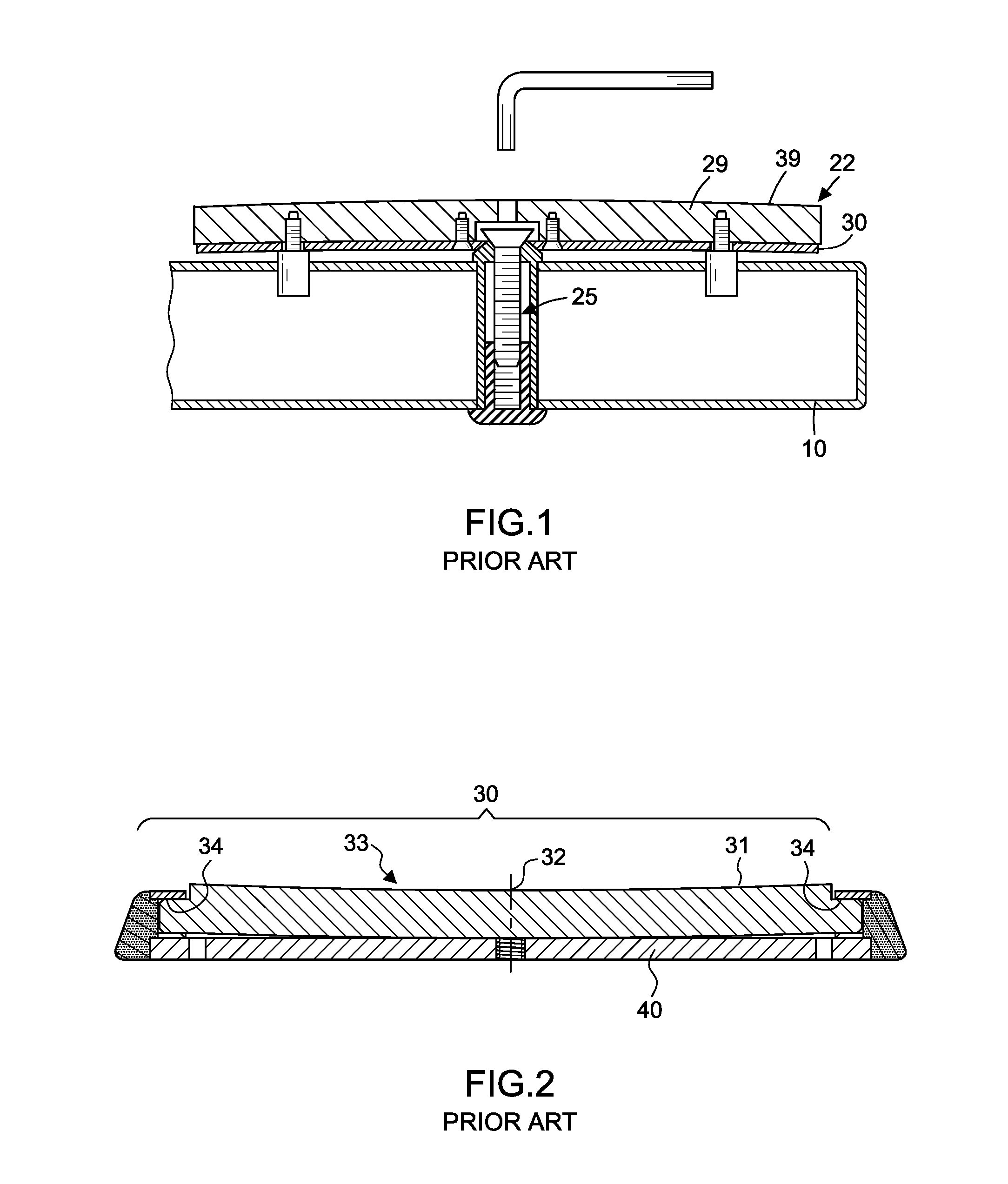
[0030]Step c: providing an attraction plate 30 with a thickness T between 10-16 mm and a length in correspondence to the length of the electric magnet 20. The attraction plate 30 also has an attraction surface 31 at a side facing the electric magnet 20.

[0031]Step d: deciding a thickness T of the attraction plate 30 to determine a height h of an arch portion 32 arran...


PUM

PropertyMeasurementUnit
Lengthaaaaaaaaaa
Lengthaaaaaaaaaa
Lengthaaaaaaaaaa

Abstract

A manufacturing method of an attraction plate for electromagnetic door locks has an attraction plate positioned on a mounted body with a positioning hole at the center thereof. The attraction plate further has an arch portion at the center thereof which is reversely proportional to a thickness thereof and the thickness thereof is pre-determined for manufacturing a different height of the arch portion thereof for better effects. With an internal stress from the curved design, a tensile value of a door lock is increased for better operation of a door lock.

Description

[0001]This patent application is a continuation-in-part of Ser. No. 14 / 726,790 filed on Jun. 14, 2015, currently pending.BACKGROUND OF THE INVENTION[0002]1. Field of the Invention[0003]The invention relates to a manufacturing method of an attraction plate for electromagnetic door locks, particularly to one that manufactures an attraction plate with two convex-curve surfaces to form a curved internal stress for door locks.[0004]2. Description of the Related Art[0005]FIG. 1 is an armature for electromagnetic locks in U.S. Pat. No. 4,957,316 disclosed by Frolov. Frolov disclosed an electromagnetic lock having an electromagnet mounted to a door frame and having an armature 22 mounted to a door 10 for attraction to the electromagnet to lock the door 10. The armature 22 has a strike plate 29 and a back plate 30. The strike plate 29 further has a recess for engagement with an end of a bolt 25, and the back plate 30 is disposed between the strike plate 29 and the door 10 and is penetrated t...

Claims


Application Information

Patent Timeline
IPC IPC(8): E05C19/16H01F7/08
CPCH01F7/08E05C19/166Y10T29/4902Y10T29/49075E05C19/168H01F41/02H01F41/0253
Inventor LIAO, YI-FAN
Owner LIAO YI FAN
Why Eureka
Try Eureka