Method and device for marking ammunition for identification or tracking

Active Publication Date: 2016-09-08
SICPA HLDG SA
View PDF46 Cites 4 Cited by
  • Summary
  • Abstract
  • Description
  • Claims
  • Application Information

AI Technical Summary

Benefits of technology

[0010]It is an aim of the present disclosure to provide a method and a device which allow for

Problems solved by technology

However, due to the limited space available on the bottom of a cartridge, the amount of information which can be applied to the cartridge via such a marking is also very limited.
The usual technique of stamping, as it is applied to the bottom of the case of the cartridge, is much less suitable for application to the case in its lateral or radial direction.
A particular drawback of this method is that the equipment needed for laser engraving is very complex and, thus, expensive, which is a decisive disadvantag

Method used


Image

  • Method and device for marking ammunition for identification or tracking
  • Method and device for marking ammunition for identification or tracking

Examples


Example

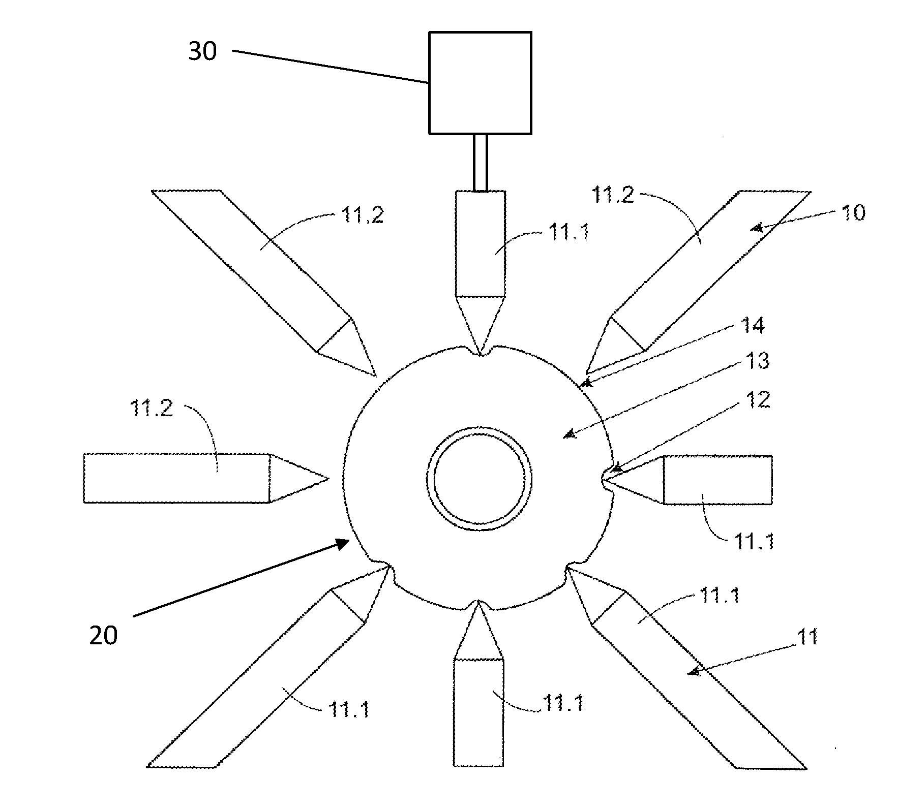
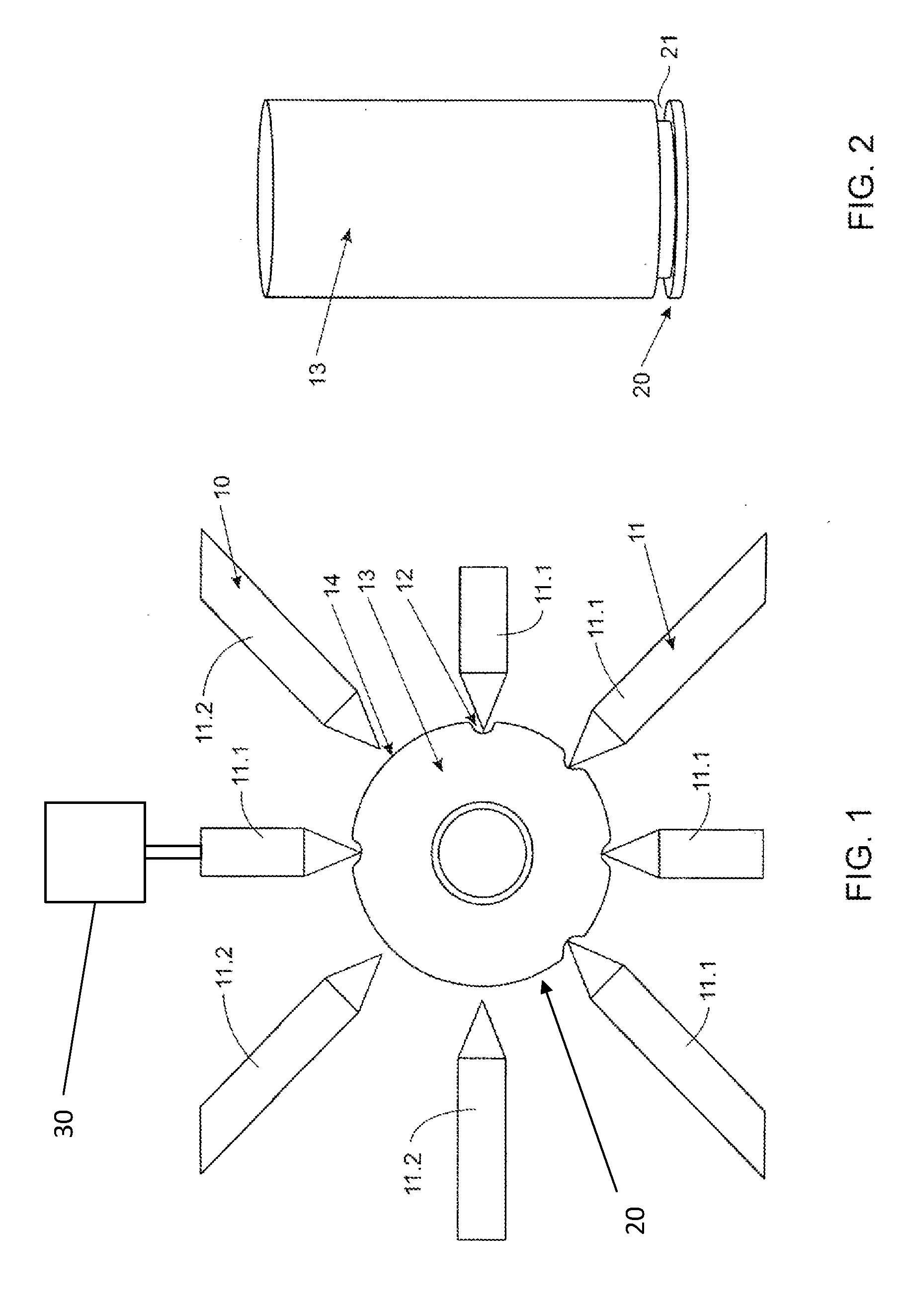
[0040]FIG. 1 illustrates a preferred method for providing a mark to a case 13 of a cartridge of ammunition. The mark comprises a plurality of sub-marks 12 which are applied to the case 13 by, in the illustrated embodiment, a plurality of indenters, e.g., compression fingers 10, which are structured and arranged to selectively radially indent a circumferential surface of a bottom 20 of the case 13.

[0041]The bottom view of the case 13 of FIG. 1 shows the bottom surface of the case 13 by which the firing pin of a gun activates the primer in the case 13 to ignite the propellant and, optionally, fire the projectile. The bottom of the case 13 is located at the end of the cartridge opposite to any projectile. This bottom surface of the case 13 can, in addition to the marks of present disclosure, be marked by a head stamp in the usual manner, as known from the prior art. Such a head stamp is, however, not illustrated in FIG. 1.

[0042]FIG. 1 illustrates that a circumference of the bottom 20 f...


PUM


Abstract

A method of providing a mark to a case of a cartridge of ammunition. The mark includes at least one sub-mark and is suitable for identification and/or for tracking of the cartridge. At least one indenter selectively radially indents a circumferential surface of a bottom of the case, thereby forming the at least one sub-mark.

Description

CROSS-REFERENCE TO RELATED APPLICATIONS[0001]The present application is a National Stage Application of International Application No. PCT / EP2014 / 070215 filed Sep. 23, 2014, which published as WO 2015 / 040236 A1 on Mar. 26, 2015, the disclosures of which are expressly incorporated by reference herein in their entireties. Further, the present application claims the benefit of U.S. provisional application No. 61 / 881,168, filed Sep. 23, 2013, the disclosure of which is expressly incorporated by reference herein in its entirety.BACKGROUND OF THE DISCLOSURE[0002]1. Field of the Disclosure[0003]The present disclosure relates to the field of marking of ammunition. In particular, the disclosure relates to a method of providing a mark to a case of a cartridge of ammunition, wherein the mark comprises at least one sub-mark and is suitable for identification or for tracking of the cartridge. Further, the disclosure relates to a device for providing such a mark to a cartridge of ammunition.[0004]...

Claims


Application Information

Patent Timeline
IPC IPC(8): B41J3/407F42B5/02
CPCF42B5/025B41J3/407F42B35/00
Inventor RAEMY, XAVIER CEDRICVASIC, MILAN
Owner SICPA HLDG SA
Why Eureka
Try Eureka