
A Wearable sports timing tag assembly

a technology of timing tags and tags, applied in the field of sports timing, can solve the problems of increasing the risk that participants that pass or cross the rfid reader are not detected by the detection antenna, and achieve the effect of avoiding or at least minimizing the interference and/or coupling effects between the tags

Active Publication Date: 2016-09-08
MYLAPS BV
View PDF9 Cites 17 Cited by
  • Summary
  • Abstract
  • Description
  • Claims
  • Application Information

AI Technical Summary

Benefits of technology

The patent relates to a sports timing tag assembly that improves the detection of participant passes during a race or other complex sporting events. The assembly uses multiple UHF tags, positioned on a flexible substrate, to ensure that at least one tag is oriented towards the RF field of the RFID reader during the passing of the RFID reader. This reduces the risk of missed passes, and the assembly allows for easy programming and verification of results. The substrate acts as a spacer, keeping the antennas away from the body of the athlete and minimizing detuning. This design improves efficiency and accuracy during sports timing.

Problems solved by technology

Hence, when using a conventional sports timing tag, the direction sensitivity of a tag in combination with the very small backscattered signal and the strong detuning due to the presence of the body of the participant increases the risk that participants that pass or cross the RFID reader are not detected by the detection antenna.

Method used


Image

  • A Wearable sports timing tag assembly
  • A Wearable sports timing tag assembly
  • A Wearable sports timing tag assembly

Examples


Embodiment Construction

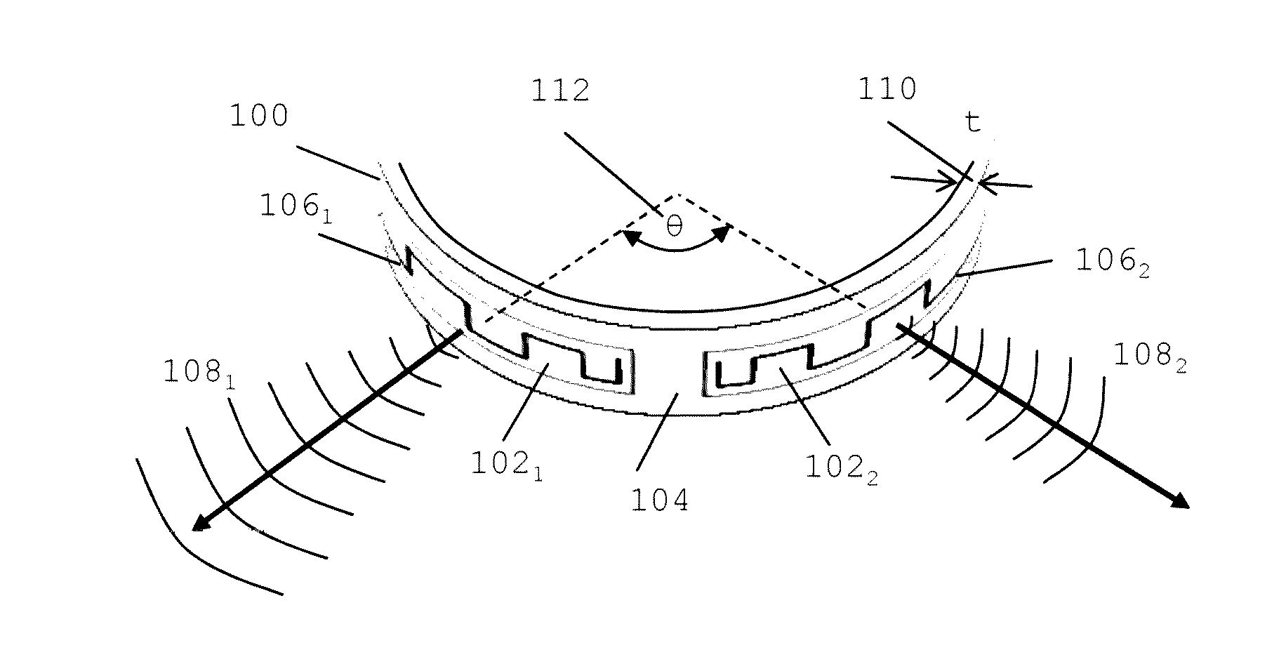
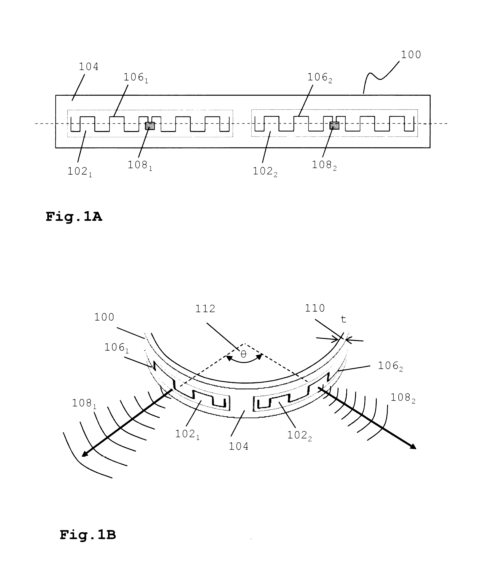
[0043]FIG. 1A and FIG. 1B show an exemplary embodiment of a sports timing tag assembly according to an embodiment of the invention. In FIG. 1A a top view of the sports timing tag assembly 100 is shown before wearing, i.e. in a substantially flat orientation. The tag assembly may comprise multiple, i.e. at least two, RFID tags 1021,2 positioned on a flexible support substrate 104 of a predetermined width and length. A tag may comprise an antenna 1061,2 (e.g. a dipole antenna) and a microprocessor 1081,2, e.g. an application specific integrated circuit (ASIC) chip. Typically UHF tags have an elongated form due to the fact that length of the antenna is about half the wavelength that needs to be detected. In this particular example, tags are positioned adjacently so that the their longitudinal axis substantially line up and are parallel to the longitudinal axis of the flexible substrate. In this configuration there is no or minimal electromagnetic coupling between the tags. It is submit...


PUM


Abstract

A wearable sport timing tag assembly comprising at least a first and second tag is described for transmitting data associated with the wearer of the tag assembly to at least one detection antenna, wherein the tag assembly comprises means for attaching the tag assembly to at least a body part or clothing of the wearer, wherein when attached to said body or clothing the main signal transmission direction of said first tag being in a first direction; and, the main signal transmission direction of said second tag being in a second direction which is different from said first direction.

Description

CROSS-REFERENCE TO RELATED APPLICATION[0001]The present application is a national stage filing of International patent application Serial No. PCT / EP2013 / 003076, filed Oct. 13, 2013, and published as WO 2015 / 051813 A1 on Apr. 16, 2015, in English.FIELD OF THE INVENTION[0002]The present invention relates to sports timing and in particular to wearable sports timing tags, wearable bands comprising a sports timing tag, a method in an RFID reader of obtaining data from a sports timing tag, and a method of programming sports timing tags.BACKGROUND[0003]The discussion below is merely provided for general background information and is not intended to be used as an aid in determining the scope of the claimed subject matter.[0004]Radio-frequency identification (RFID) is a wireless technique, which uses radio-frequency electromagnetic (EM) fields to transfer data for the purposes of automatically identifying and tracking tags attached to objects. A battery-less tag, usually referred to as passi...

Claims


Application Information

Patent Timeline
IPC IPC(8): G06K7/10G07C1/24
CPCG07C1/24G06K7/10366G06K19/07766
Inventor VAN RENS, BAS JAN EMILEWILLEMSE, JEROEN JOHANVERWOERD, ADRIAAN KLAAS
Owner MYLAPS BV
Learn More