MEMS device, liquid ejecting head, and liquid ejecting apparatus

a liquid ejector and ejector technology, applied in printing and other directions, can solve the problems of no longer being able to correctly drive piezoelectric actuators, no longer being able to electrically connect bonding wires, and adhesion entering the interconnect pattern, etc., and achieve the effect of secure connection

Active Publication Date: 2016-09-15
SEIKO EPSON CORP
View PDF1 Cites 4 Cited by
  • Summary
  • Abstract
  • Description
  • Claims
  • Application Information

AI Technical Summary

Benefits of technology

[0011]An advantage of some aspects of the invention is to provide a MEMS device capable of driving a pressure generating unit with a more secure connection between a driving circuit and an interconnect pattern, and a liquid ejecting head and liquid ejecting apparatus capable of ejecting a liquid in a reliable manner.

Problems solved by technology

However, there is a risk that adhesive will enter into the interconnect pattern, the periphery thereof, and so on from between the sealing substrate and the protective substrate and reach the region where the bonding wires of the interconnect pattern are connected.
If that region is covered by adhesive, there is a risk that the bonding wires can no longer be electrically connected and the piezoelectric actuator can no longer be driven correctly.
It should be noted that this problem is not limited to liquid ejecting heads that eject liquid, and also arises in the same manner in other MEMS devices aside from liquid ejecting heads.

Method used


Image

  • MEMS device, liquid ejecting head, and liquid ejecting apparatus
  • MEMS device, liquid ejecting head, and liquid ejecting apparatus
  • MEMS device, liquid ejecting head, and liquid ejecting apparatus

Examples


first embodiment

[0033]The invention will be described in detail based on embodiments. An ink jet recording head will be given as an example of a liquid ejecting head, and may also be called simply a “recording head”. An ink jet recording apparatus will be given as an example of a liquid ejecting apparatus.

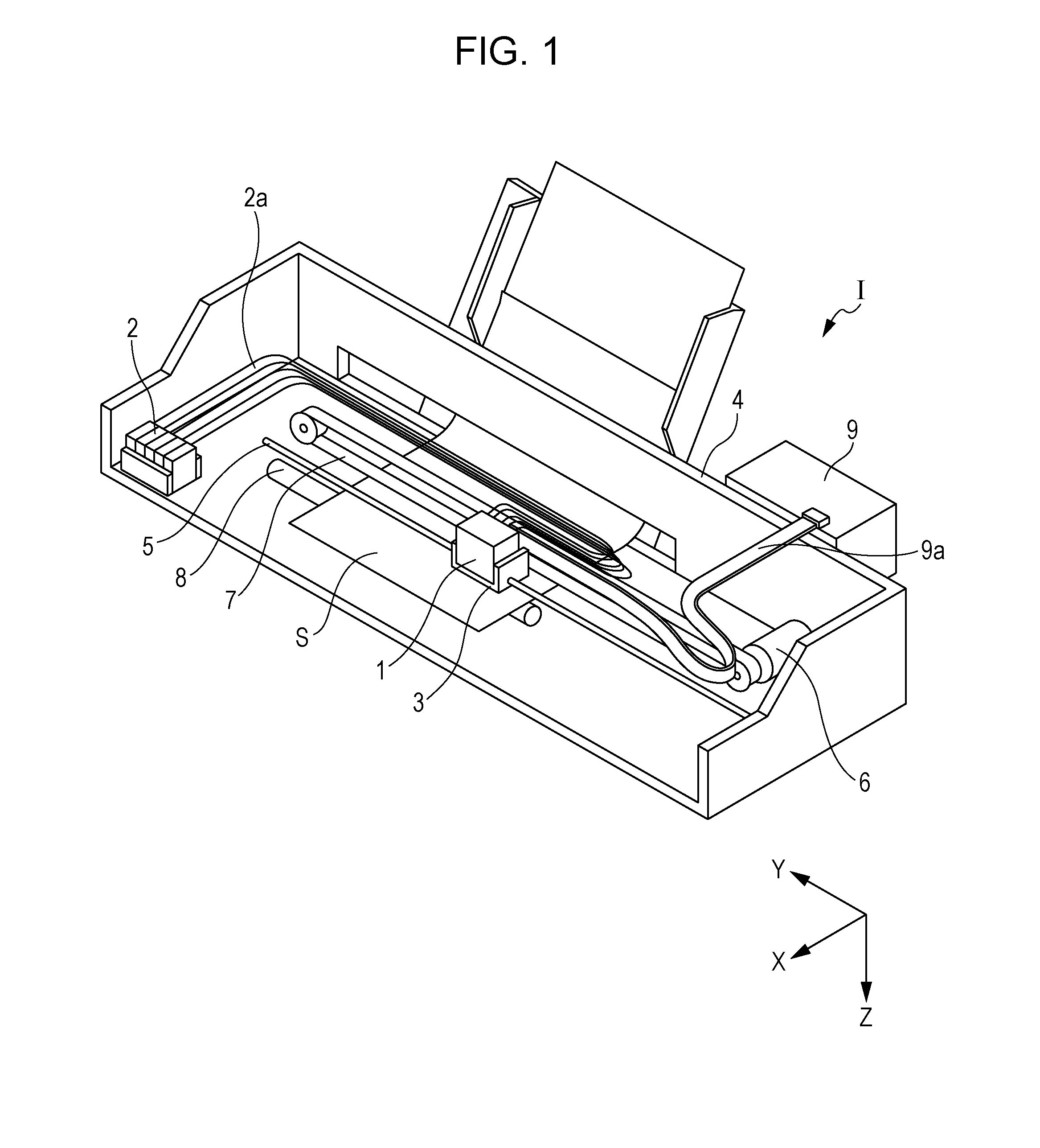
[0034]FIG. 1 is a schematic diagram illustrating an ink jet recording apparatus according to the invention. In an ink jet recording apparatus I, an ink jet recording head unit 1 (also called a “head unit 1” hereinafter) is mounted in a carriage 3. The carriage 3 in which the head unit 1 is mounted is provided so as to be mobile in the axial direction of a carriage shaft 5 attached to an apparatus main body 4.

[0035]Liquid holding units 2 constituted by ink tanks or the like that hold ink are provided in the apparatus main body 4, and ink from the liquid holding units 2 is supplied to the head unit 1 mounted in the carriage 3 via supply pipes 2a such as tubes or the like. Note that in this embodimen...

second embodiment

[0093]Although the recording head 220 according to the first embodiment suppresses the adhesive 46 from advancing into the connection region 115 by providing the groove 114 in the connection portion 112, the recording head is not limited thereto. FIGS. 10A and 10B are plan views of the vicinity of a connection portion of an interconnect pattern according to this embodiment. Note that elements identical to those in the first embodiment are given the same reference numerals, and redundant descriptions thereof will be omitted.

[0094]As illustrated in FIG. 10A, a connection portion 112A of the interconnect pattern 110A according to this embodiment includes a linear portion 116 provided between the border 140 and the connection region 115, branching portions 117 that branch off from the linear portion 116, and the connection region 115 partially surrounded by the groove 114. A portion constituted by the groove 114 and the connection region 115 will be called a connection main body portion...


PUM


Abstract

A MEMS device includes a protective substrate on which is mounted a driving circuit that drives a piezoelectric actuator and on which is formed an interconnect pattern electrically connected to the driving circuit, and a sealing substrate that includes a first opening and that is bonded to the protective substrate using an adhesive so that part of the interconnect pattern is located between the protective substrate and the sealing substrate. The interconnect pattern includes a connection portion that extends from a bonding region where the protective substrate and the sealing substrate are bonded by the adhesive to the first opening, and that has a connection region electrically connected to the driving circuit. A groove is formed in the connection portion between the connection region and a border between the bonding region and the connection portion.

Description

BACKGROUND[0001]1. Technical Field[0002]The present invention relates to MEMS devices, liquid ejecting heads, and liquid ejecting apparatuses, and particularly relates to ink jet recording heads and ink jet recording apparatuses that eject ink as a liquid.[0003]2. Related Art[0004]There is a liquid ejecting head, which is an example of a device including a MEMS (Micro Electro Mechanical Systems) device, that includes a flow channel formation substrate in which pressure generation chambers communicating with corresponding nozzle openings that eject a liquid are formed, piezoelectric actuators provided on one surface side of the flow channel formation substrate, a protective substrate bonded to the piezoelectric actuator side of the flow channel formation substrate, a driving circuit that drives the piezoelectric actuators, and a manifold that serves as a common liquid chamber for the pressure generation chambers.[0005]The driving circuit is disposed on one surface of the protective s...

Claims


Application Information

Patent Timeline
Patent Type & Authority Applications(United States)
IPC IPC(8): B41J2/14
CPCB41J2/14B41J2/01B41J2/14233B41J2002/14362B41J2002/14491
Inventor YASOSHIMA, TAKESHIKAMIJO, TAKAHIROARUGA, KOJIMIKOSHIBA, MASANORI
Owner SEIKO EPSON CORP
Why Eureka
Try Eureka