Molded plastic needle stick accident prevention dispenser

Inactive Publication Date: 2016-09-22
BIOMEDICAL POLYMERS
View PDF40 Cites 1 Cited by
  • Summary
  • Abstract
  • Description
  • Claims
  • Application Information

AI Technical Summary

Benefits of technology

[0006]In aspects of the invention, the sharp end of the spike tube resides below the dispenser skirt to prevent a needle stick accident and to prevent the transfer of blood borne pat

Problems solved by technology

Conventional dispensers can be awkward to use with such systems.
After use, a danger ex

Method used


Image

  • Molded plastic needle stick accident prevention dispenser
  • Molded plastic needle stick accident prevention dispenser
  • Molded plastic needle stick accident prevention dispenser

Examples


Example

[0016]Aside from the preferred embodiment or embodiments disclosed below, this invention is capable of other embodiments and of being practiced or being carried out in various ways. Thus, it is to be understood that the invention is not limited in its application to the details of construction and the arrangements of components set forth in the following description or illustrated in the drawings. If only one embodiment is described herein, the claims hereof are not to be limited to that embodiment. Moreover, the claims hereof are not to be read restrictively unless there is clear and convincing evidence manifesting a certain exclusion, restriction, or disclaimer.

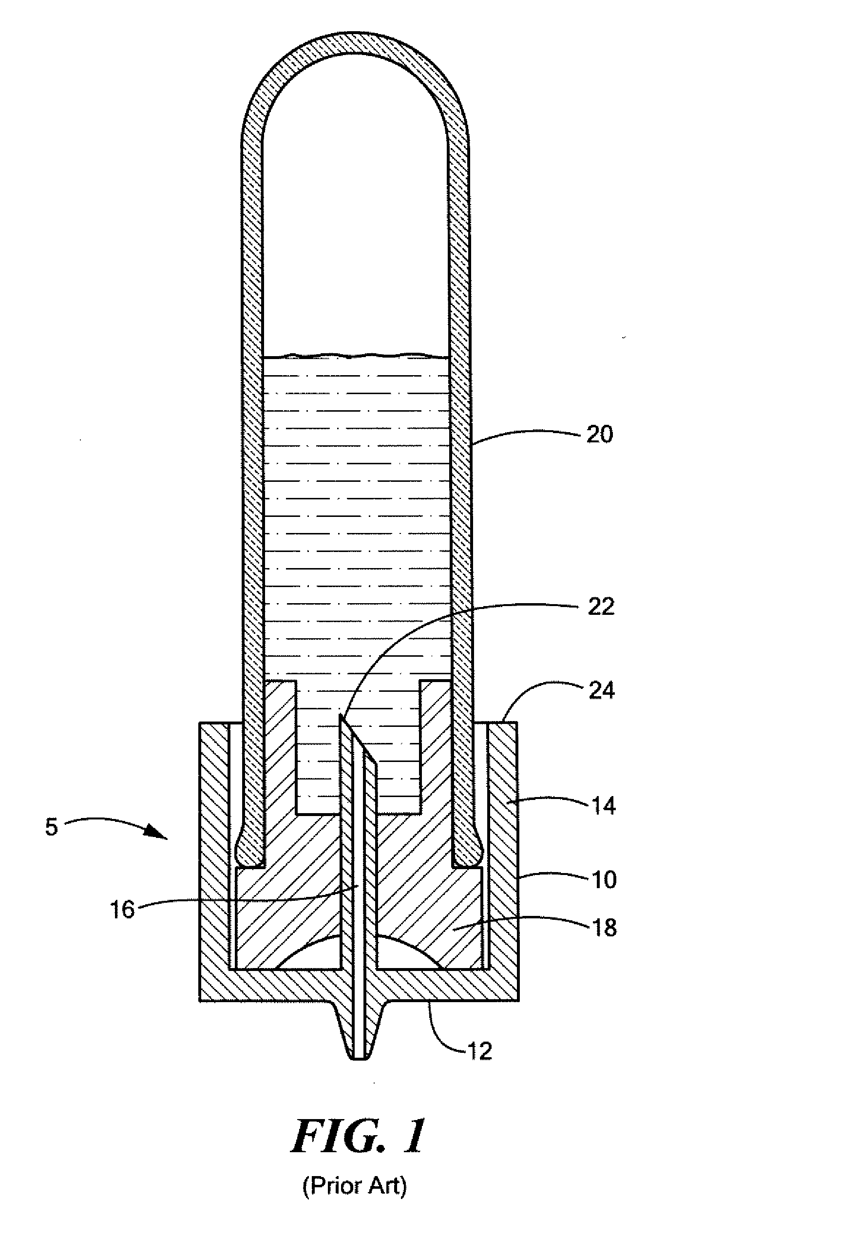
[0017]FIG. 1 show the design of the dispensers of U.S. Pat. No. 5,163.583 with body 10 defining disk 12, skirt 14, and spike tube 16 shown pushed through stopper 18 of test tube 20. Spike tube 16 is designed so stopper 18 seats on disk 12. As such, the distal pointed end 22 of spike tube 22 is long enough so it is at or nea...


PUM


Abstract

A molded plastic dispenser includes a disk and a skirt extending upwards from the disk defining a receptacle for receiving a test tube stopper therein. A spike tube extends from the disk into the receptacle and includes a distal sharpened end and a seat between the disk and the distal sharpened end for engaging the stopper. The skirt has a top rim disposed above the distal sharpened end of the spike tube.

Description

FIELD OF THE INVENTION[0001]This invention relates to a blood dispenser for transferring blood from a stoppered test tube to a slide or blood analyzer cartridge.BACKGROUND OF THE INVENTION[0002]Various dispensers have been designed to transfer blood and other biological fluids from a stoppered test tube to a slide. Most dispensers have some kind of a base and a cannula extending outwardly therefrom. U.S. Pat. Nos. 5,697,522 and 5,344,666, both incorporated herein by this reference, disclose bases with a plurality of stabilizing legs. U.S. Pat. No. 5,163,583, also incorporated herein by this reference, discloses a different design with a skirt about the cannula which is supported by a solid disk. See also the Helena Laboratory Corp's. “H-Pette” products.[0003]The state of the art in blood analyzers includes a cartridge with a blood entry port. A dispenser is used to transfer one or two drops of blood from a stoppered test tube to the cartridge via the blood entry port thereof. The ca...

Claims


Application Information

Patent Timeline
IPC IPC(8): B01L9/06B65D51/22
CPCB01L9/06B65D51/22B01L2200/085B01L2300/12B01L2300/0672B01L2300/0803B01L2200/141B01L3/561B01L3/563
Inventor MILLER, WAYNE
Owner BIOMEDICAL POLYMERS
Why Eureka
Try Eureka