

Image Carrier Cleaning Device, Image Carrier Cleaning Method, and Image Forming Apparatus
- Summary
- Abstract
- Description
- Claims
- Application Information
AI Technical Summary
Benefits of technology
Problems solved by technology
Method used
Image

Examples
Embodiment Construction
[0020]Hereinafter, an exemplary embodiment of the invention will be described with reference to the accompanying drawings.
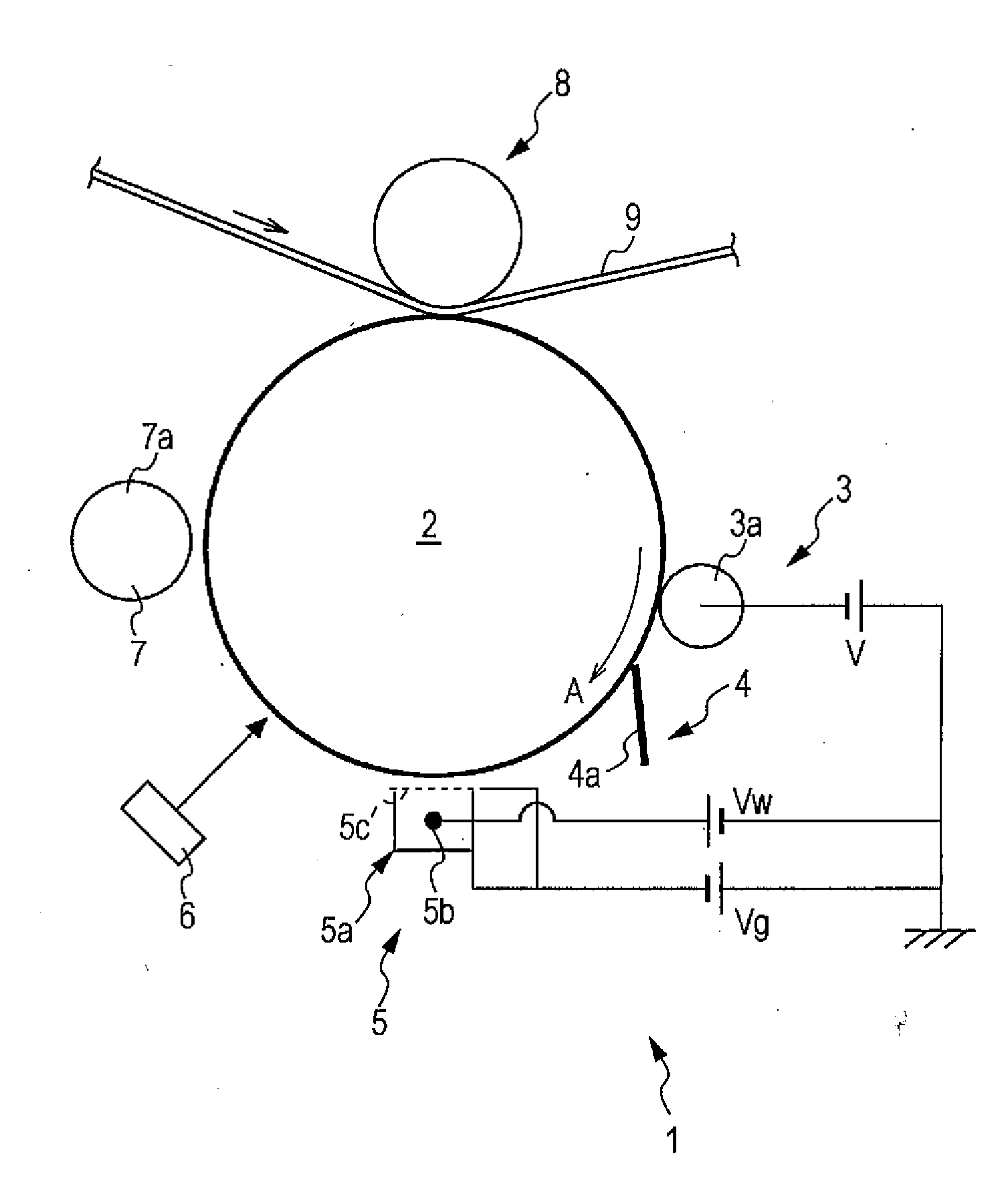
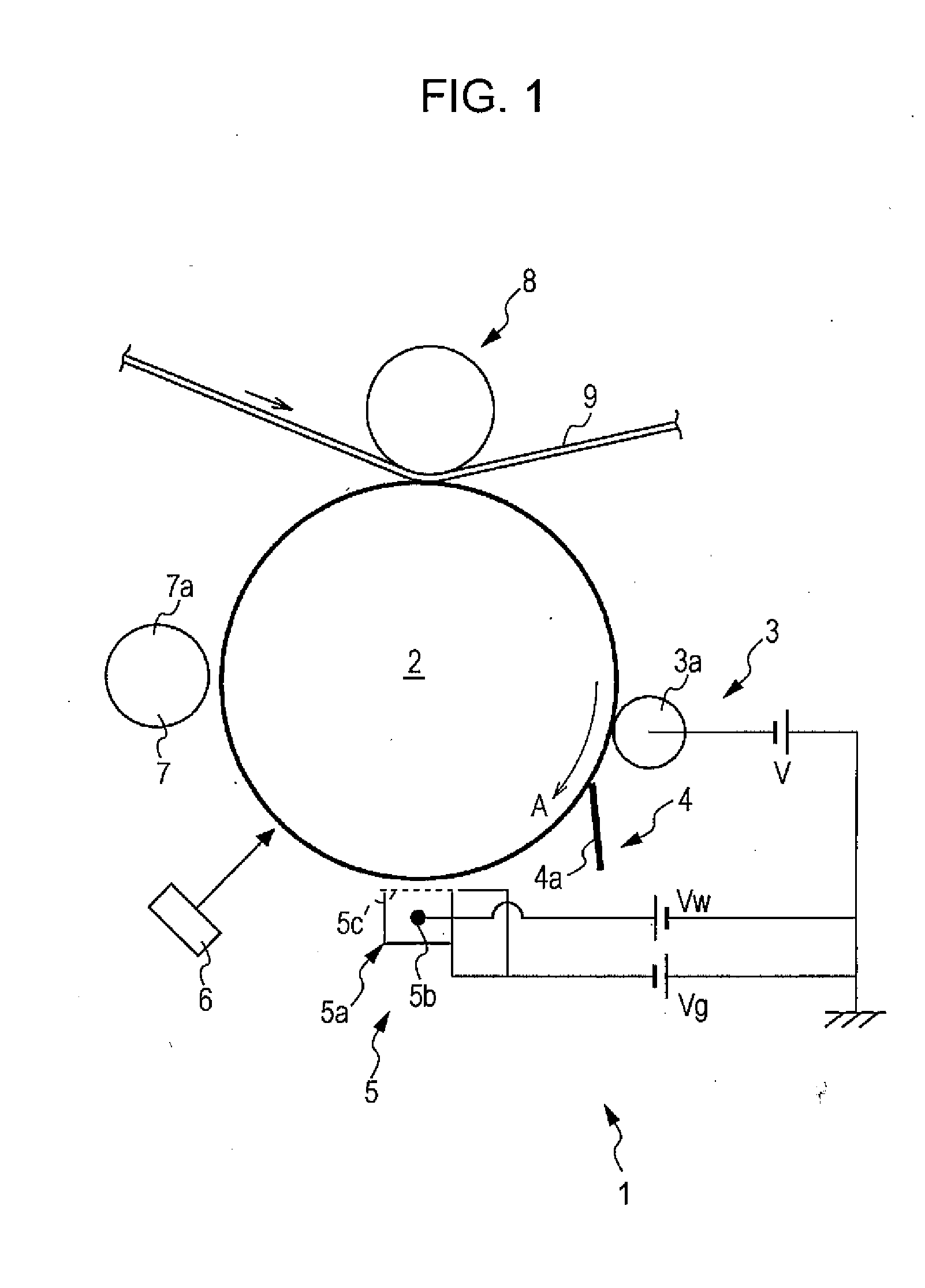
[0021]FIG. 1 is a diagram schematically and partially showing an image forming apparatus according to an example of an embodiment of the invention.
[0022]In an image forming apparatus 1 shown in the example, an image forming operation is carried out by a negatively charged toner. Of course, the image forming operation may be carried out by a positively charged toner. In the below description, the image forming apparatus 1 uses the negatively charged toner. However, in the case of the positively charged toner, the potential of the charging operation of each of the members to be described later may have the opposite polarity. In addition, the toner includes a toner mother particle and an external additive added to the toner mother particle, but in the below description, the toner mother particle is simply referred to as toner.
[0023]As shown in FIG. 1, the image form...
PUM
 Abstract
Description
Claims
Application Information