

Optical reception apparatus, optical transmission apparatus, optical communication system, optical communication method, and storage medium storing program
- Summary
- Abstract
- Description
- Claims
- Application Information
AI Technical Summary
Benefits of technology
Problems solved by technology
Method used
Image

Examples
first exemplary embodiment
[0048]Overview of the first exemplary embodiment of the present invention will be explained with reference to drawings. It should be noted that the reference symbols in the drawings appended to this overview are attached to the elements as an example for the sake of convenience in order to help understanding, and are not intended to limit, in any way, the description of this overview.
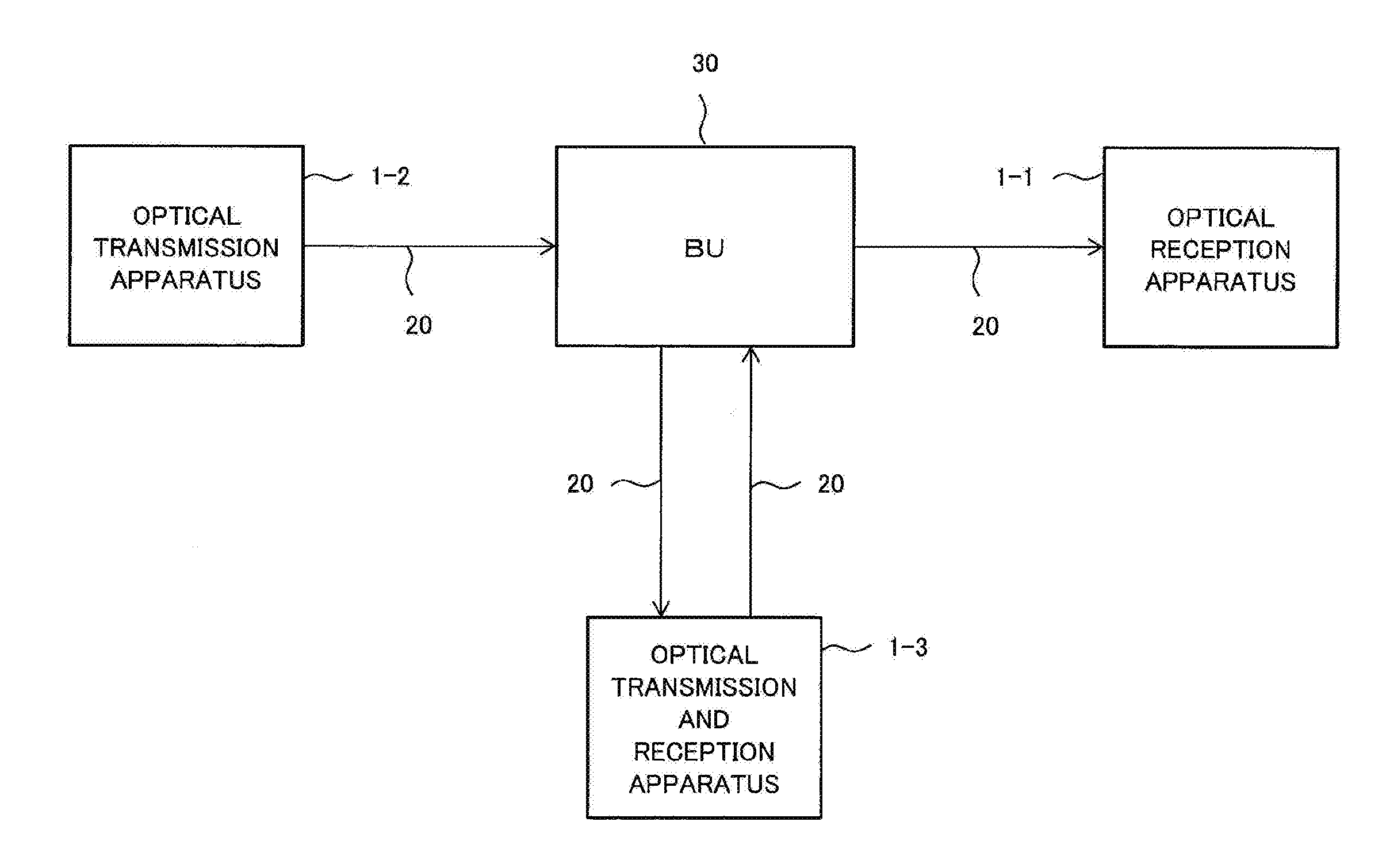
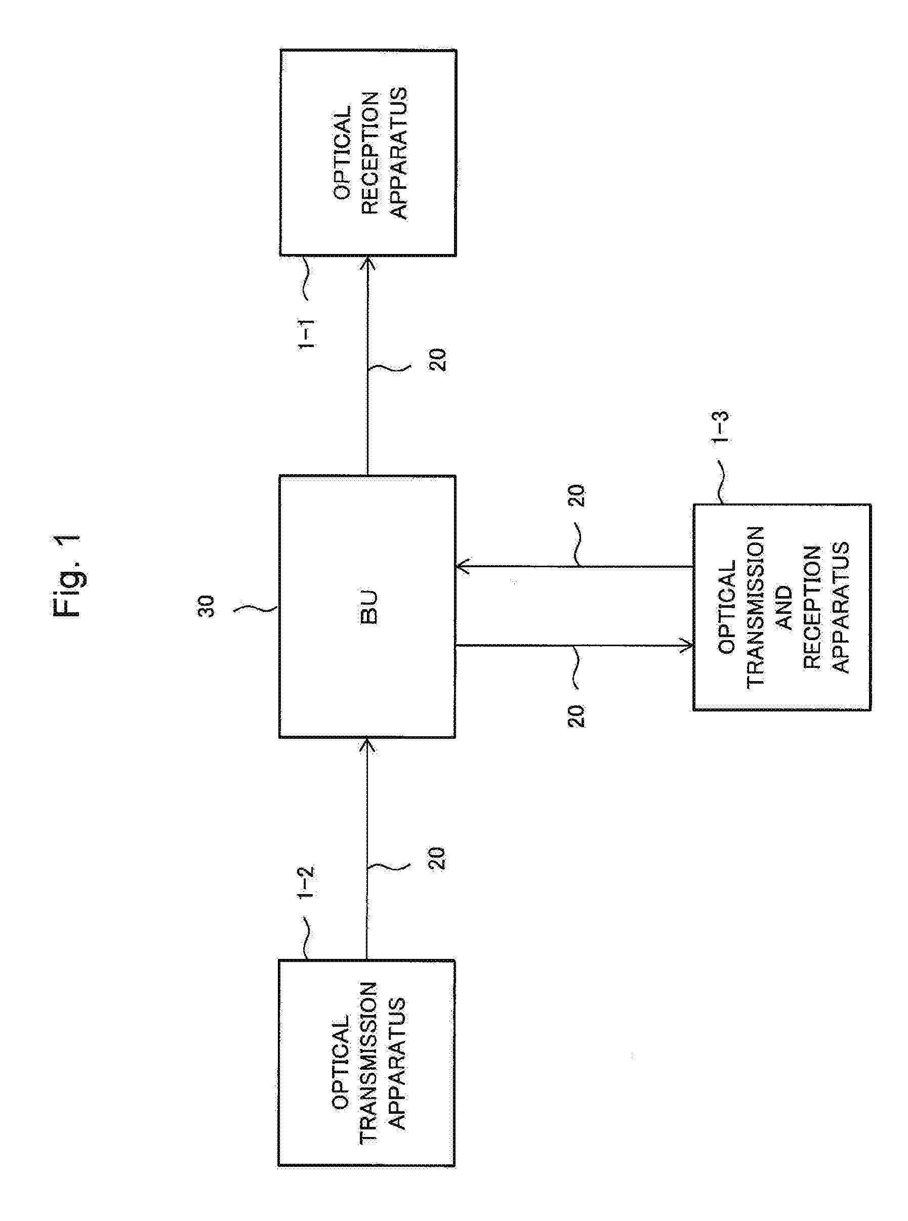
[0049]FIG. 1 is an example of a configuration of an optical communication system according to the first exemplary embodiment of the present invention. As shown in FIG. 1, the optical communication system includes an optical reception apparatus 1-1 receiving a wavelength multiplexed signal light, an optical transmission apparatus 1-2 transmitting wavelength multiplexed signal light, and an optical transmission and reception apparatus 1-3 transmitting and receiving wavelength multiplexed signal light. Further, the optical communication system includes a transmission path 20 transmitting wavelength multipl...
second exemplary embodiment
[0056]Overview of the second exemplary embodiment of the present invention will be explained with reference to drawings.
[0057]The example of a configuration of the optical communication system according to the second exemplary embodiment of the present invention is the same as that of FIG. 1.
[0058]FIG. 4 is a figure illustrating an example of a configuration of the optical reception apparatus 1-1. The configuration of optical reception apparatus 1-1 includes a transmission unit 12, a comparison unit 13, a storage unit 14, an input unit 15, and a demultiplexing unit 16.
[0059]The demultiplexing unit 16 demultiplexes the wavelength multiplexed signal light received from the transmission path 20, and outputs the optical signal of the predetermined wavelength according to the input unit 15 to the input unit 15.
[0060]The reception unit 15 converts the optical signal received from the demultiplexing unit 16 into an electric signal, and outputs the electric signal to the comparison unit 13....
third exemplary embodiment
[0077]Overview of the third exemplary embodiment of the present invention will be explained with reference to drawings.
[0078]FIG. 8 is a figure illustrating an example of a configuration of the optical reception apparatus 1-1. The optical reception apparatus 1-1 includes a transmission unit 12, a comparison unit 13, a storage unit 14, an input unit 15, a demultiplexing unit 16, and a pattern generation unit 18.
[0079]It should be noted that the optical reception apparatus 1-1 may be the branch unit 17 in place of the demultiplexing unit 16, but in the following explanation, a case where the optical reception apparatus 1-1 is the demultiplexing unit 16 will be explained as an example.
[0080]The comparison unit 13 compares the identifier (comparison information) stored in advance in the storage unit 14 and the identifier included in the electric signal received from the input unit 15.
[0081]Further, in a case where the identifier included in the electric signal and the comparison informa...
PUM
 Abstract
Description
Claims
Application Information