Side plate unit and centrifugal projector

a projector and side plate technology, applied in the direction of rotor blades, metal-working apparatus, manufacturing tools, etc., can solve the problems of inefficiency, inconvenient use, and inability to adapt to situations, and achieve the effect of raising the projection efficiency

Active Publication Date: 2016-09-22
SINTOKOGIO LTD
View PDF12 Cites 1 Cited by
  • Summary
  • Abstract
  • Description
  • Claims
  • Application Information

AI Technical Summary

Benefits of technology

[0015]The present invention can concentrate projection pattern of the projection material, and raise projection efficiency relative to a narrow projection range.

Problems solved by technology

Nozzle projectors are efficient when the projection range is narrow in width, but are not suited to situations where the projection range is wide.
Centrifugal projectors are efficient when the projection range is wide, but were inefficient and ill-suited to situations where the projection range was narrow.
In other words, in centrifugal projectors it was difficult to concentrate the projection pattern and raise projection efficiency.

Method used


Image

  • Side plate unit and centrifugal projector
  • Side plate unit and centrifugal projector
  • Side plate unit and centrifugal projector

Examples


Embodiment Construction

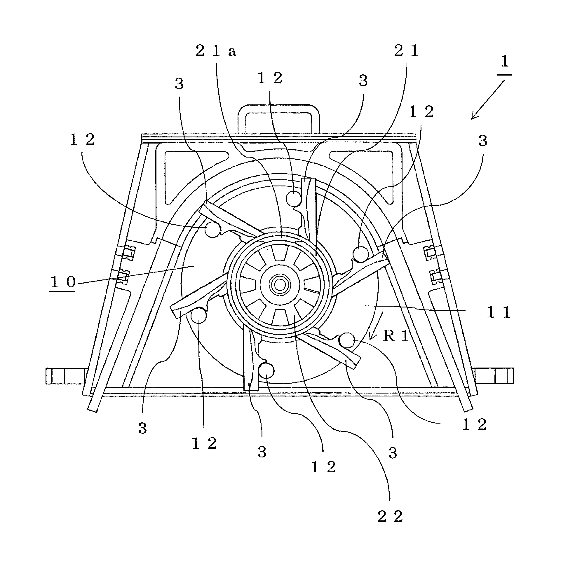
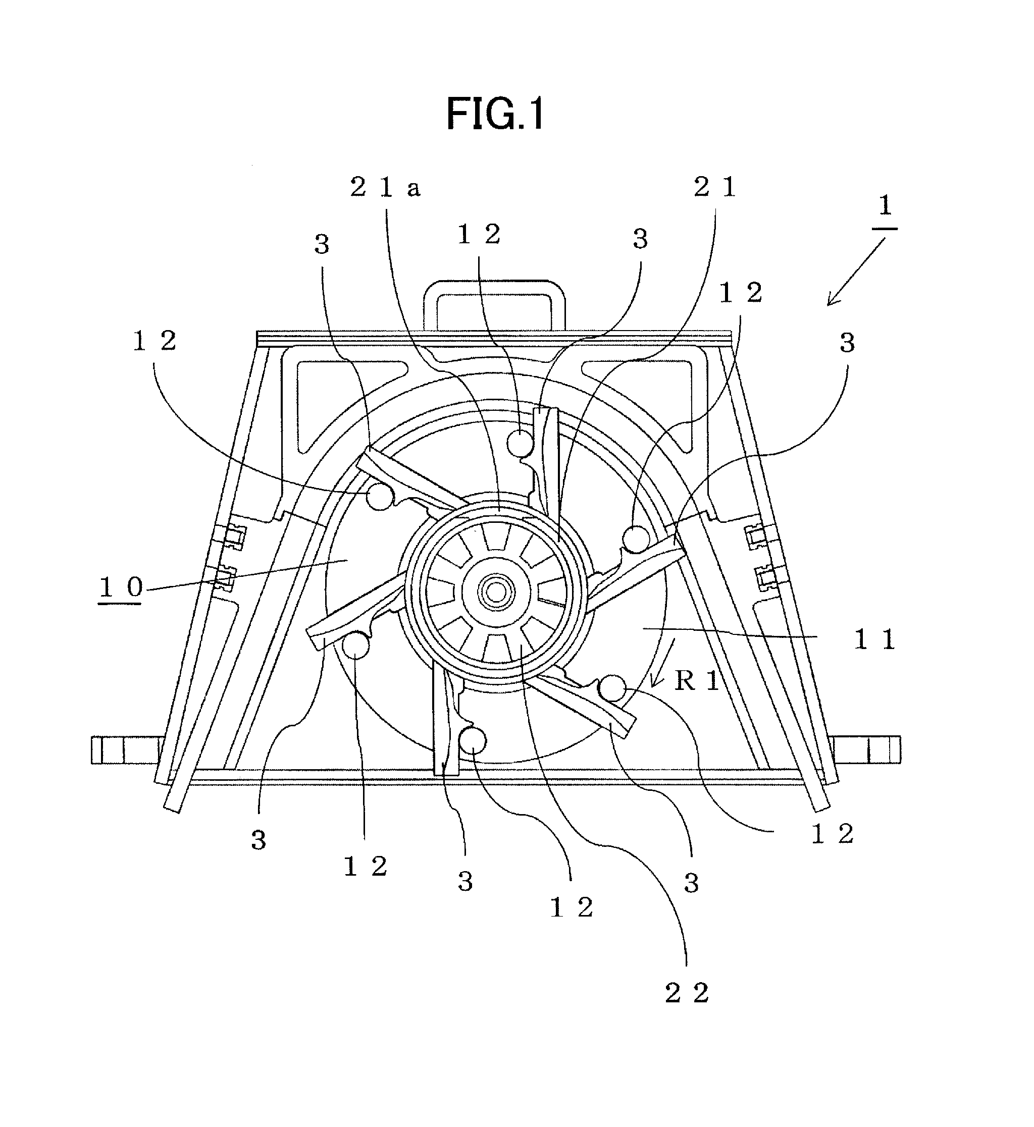
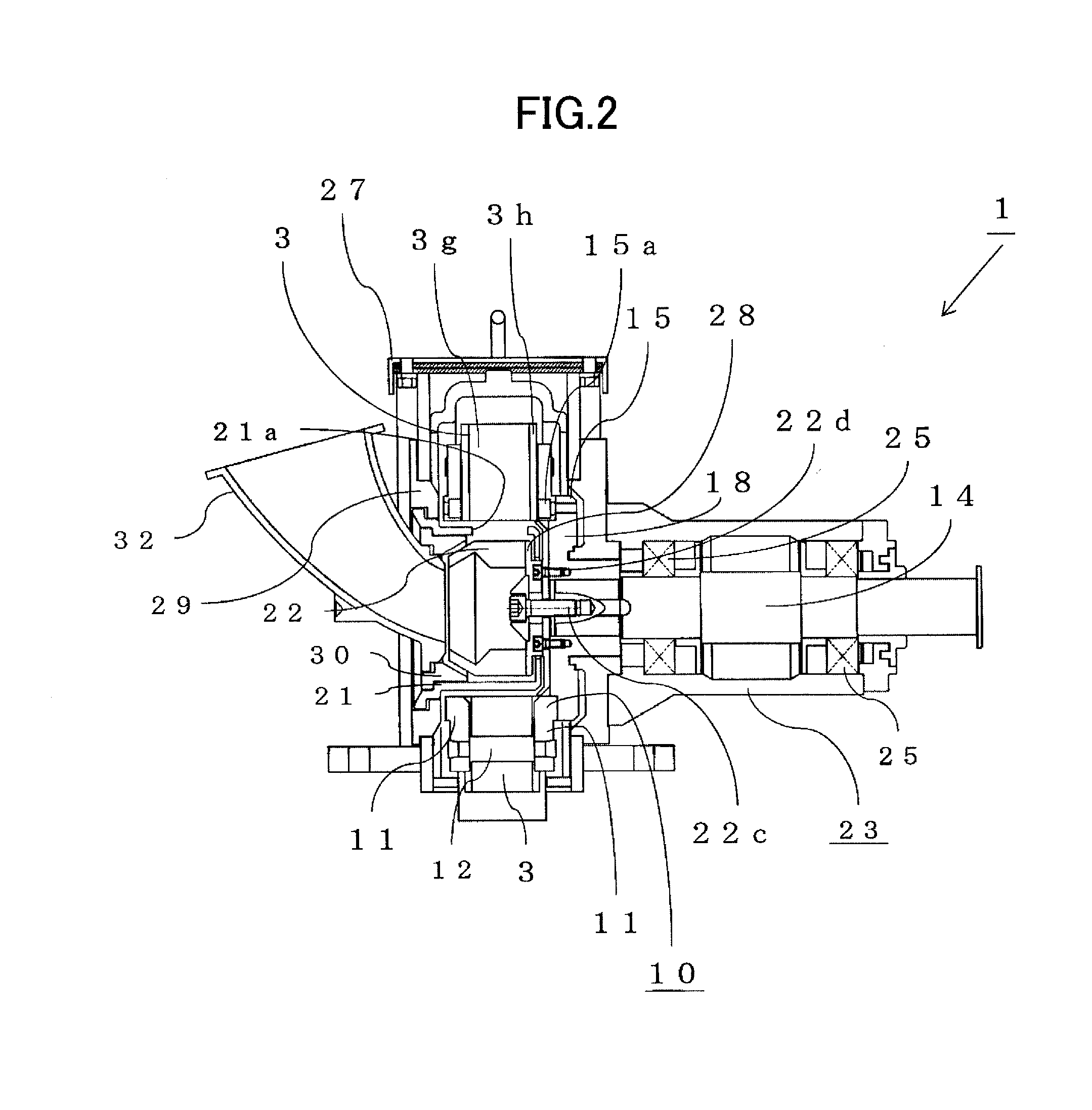
[0029]Below, referring to drawings, a centrifugal projector according to embodiments of the present invention is explained. As shown in FIGS. 1 through 3, a centrifugal projector 1 according to an embodiment of the present invention comprises a plurality of blades 3; the blades 3 are rotated and projection material 2 (“projection material” is also referred to below as “shot”) is projected by centrifugal force.

[0030]As shown in FIGS. 3 through 5, the projection surface 3a of each blade 3 has a first part 3b forming the radial inner part of the projection surface 3a, and a second part 3c, positioned radially outside the first part 3b and forming the outer part of the projection surface 3a. The second part 3c of the blade 3 is disposed as an integral part of the first part 3b, mediated by a bend or curved portion relative to the first part 3b. In the blade 3 explained here, the first part 3b and second part 3c are disposed through a curved portion 3d. The shape explained here is the sh...


PUM


Abstract

The present invention is a side plate unit (10) used in a centrifugal projector (1) which projects projection material (2) toward a processing target by rotating a plurality of blades (3), and the side plate unit (10) being provided to attach the plurality of blades thereto, the side plate unit (10) comprising: a pair of side plates (11); and a joining member (12) for joining the pairs of side plates; wherein guide channel portions (13) are respectively formed on mutually opposing surfaces of the pair of side plates (11); and the side plate guide channel portions (13) are formed to be pitched so that the radial outer side thereof is positioned to a rear in the rotational direction (R1) compared to the radial inner side thereof.

Description

TECHNICAL FIELD[0001]The present invention relates to a centrifugal projector for projecting projection material toward a processing target, and a blade used for the same.BACKGROUND ART[0002]Conventionally, centrifugal projectors and nozzle projectors have been known as projectors used in shot blasting, shot peening, and the like. A centrifugal projector is an apparatus which utilizes centrifugal force. A nozzle projector is an apparatus which utilizes air pressure. Nozzle projectors are efficient when the projection range is narrow in width, but are not suited to situations where the projection range is wide.[0003]Centrifugal projectors are efficient when the projection range is wide, but were inefficient and ill-suited to situations where the projection range was narrow. In other words, in centrifugal projectors it was difficult to concentrate the projection pattern and raise projection efficiency. Here the term “projection pattern” means the distribution of the percentage of the ...

Claims


Application Information

Patent Timeline
Patent Type & Authority Applications(United States)
IPC IPC(8): B24C5/06
CPCB24C5/06B24C5/062B24C5/064
Inventor SUZUKI, HIROAKIUMEOKA, MASATO
Owner SINTOKOGIO LTD
Why Eureka
Try Eureka