
Automatic transmission for vehicle

Active Publication Date: 2016-09-22
TOYOTA JIDOSHA KK +1
View PDF0 Cites 4 Cited by
  • Summary
  • Abstract
  • Description
  • Claims
  • Application Information

AI Technical Summary

Benefits of technology

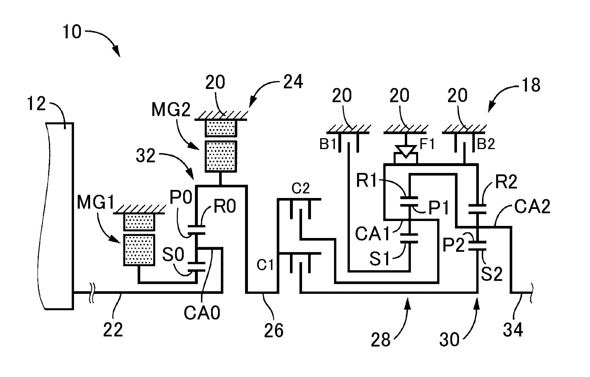
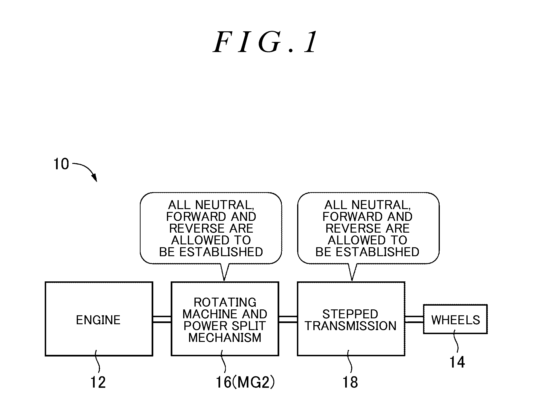
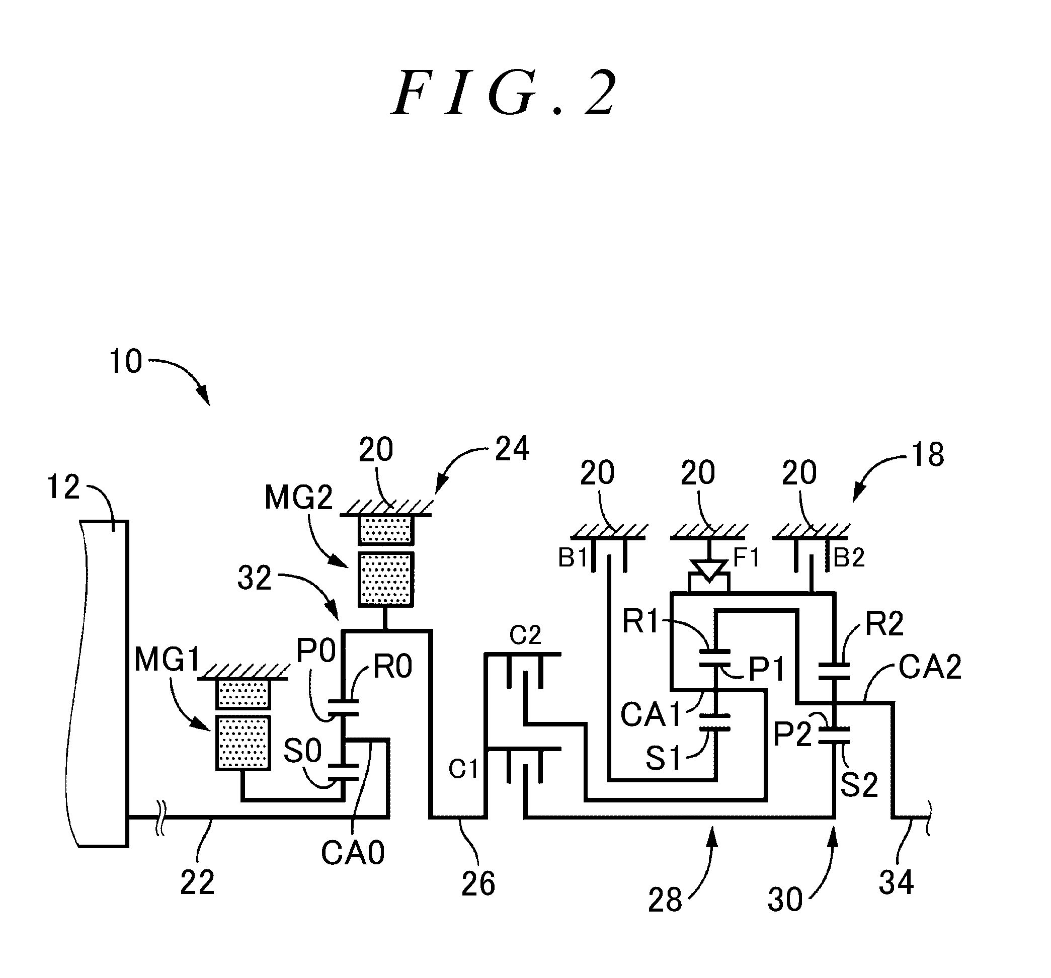
The disclosure provides an automatic transmission for a vehicle that prevents or reduces shock in the event of a failure of the electromagnetic valve. The transmission has a hydraulic controller that includes an electromagnetic valve and an oil passage switching device. The oil passage switching device is configured to switch between a state where hydraulic pressure is supplied to the oil passage and a state where supply of hydraulic pressure is cut off. This prevents the hydraulic pressure from being supplied to the engagement element when there is a failure in the electromagnetic valve, which can prevent or reduce shock in the vehicle. The non-forward range includes reverse range, parking range, and neutral range, and the oil passage switching device is configured to switch between these ranges accordingly to prevent or reduce shock in the vehicle.

Problems solved by technology

However, in the existing technique, when there occurs a failure in an electromagnetic valve that controls hydraulic pressure that is supplied to the stepped transmission and, as a result, a gear position higher than or equal to the second gear position is established while the vehicle is moving backward, the stepped transmission enters a locked state to generate braking force because of the disabled reverse rotation of the output shaft.
That is, shock occurs due to rapid deceleration of the vehicle.
The above-described inconvenience was newly found in process in which the inventors had been continuing a diligent study with the intention to improve the performance of an automatic transmission for a vehicle.

Method used


Image

  • Automatic transmission for vehicle
  • Automatic transmission for vehicle
  • Automatic transmission for vehicle

Examples


Embodiment Construction

[0027]The stepped transmission is suitably a stepped automatic transmission that includes a plurality of hydraulic friction engagement devices and that selectively establishes any one of a plurality of gear positions in response to a combination of engaged or released states of those hydraulic friction engagement devices.

[0028]The gear position in which the vehicle is allowed to move backward is suitably a first gear position, that is, a gear position having the largest speed ratio, in the stepped transmission. The gear position in which the vehicle is not allowed to move backward is suitably a gear position higher than or equal to a second gear position, that is, a gear position having a smaller speed ratio than the first gear position, in the stepped transmission.

[0029]The stepped transmission suitably includes a one-way clutch that is provided between a rotating element and a non-rotating member in the stepped transmission and that permits rotation of the rotating element in one ...


PUM


Abstract

In a non-forward range, the same gear position as a forward first gear position is established in a stepped transmission. A hydraulic controller includes a second linear solenoid valve and third linear solenoid valve that respectively supply hydraulic pressure to a second clutch and first brake, and a selector valve that is provided in an oil passage upstream of the second and third linear solenoid valves and that switches between a state where hydraulic pressure is supplied to the oil passage and a state where supply of hydraulic pressure is cut off. When the non-forward range is set or when a vehicle is moving backward, the selector valve cuts off supply of hydraulic pressure to the oil passage. Thus, when there is a failure in the second or third linear solenoid valve, it is possible to suitably establish a gear position wherein the vehicle is not allowed to move backward.

Description

INCORPORATION BY REFERENCE[0001]The disclosure of Japanese Patent Application No. 2015-058794 filed on Mar. 20, 2015 including the specification, drawings and abstract is incorporated herein by reference in its entirety.BACKGROUND[0002]1. Field[0003]The disclosure relates to an automatic transmission for a vehicle and, more particularly, to improvement for preventing or reducing shock in the event of a failure of an electromagnetic valve.[0004]2. Description of Related Art[0005]A known automatic transmission for a vehicle includes a rotating machine and a stepped transmission. In the automatic transmission, the rotating machine and the stepped transmission are provided in series with each other in a power transmission path between a drive source and wheels. There has been suggested the following technique intended for such an automatic transmission for a vehicle. The same combination of engaged or released states of engagement elements in the stepped transmission is used for both a ...

Claims


Application Information

Patent Timeline
IPC IPC(8): F16H61/02B60K6/547F16H61/00F16H61/12
CPCF16H61/0265F16H61/0021B60K6/547B60Y2400/406B60Y2200/92B60Y2400/70Y10S903/919F16H47/00B60K6/365B60K6/383B60K6/387B60K6/445F16H3/728B60K2006/381F16H2200/2041F16H2200/2066F16H3/66F16H2003/445F16H2200/0043F16H2200/2007F16H2200/2082F16H59/105F16H61/12F16H2061/1252Y02T10/62F16H61/16
Inventor FUJII, KOTAOKUDA, KOICHITABATA, ATSUSHISUZUKI, HARUHISAMATSUBARA, TOORUNODA, KAZUYUKIHYODO, YOSHIMITSUTANAKA, KOUSUKE
Owner TOYOTA JIDOSHA KK
Learn More