
Point-of-use-activated microbattery and biocompatible electronic device incorporating the same

Active Publication Date: 2016-09-22
QUANTUM MEDICAL INNOVATIONS LLC
View PDF1 Cites 12 Cited by
  • Summary
  • Abstract
  • Description
  • Claims
  • Application Information

AI Technical Summary

Benefits of technology

The patent describes a smart contact lens that can be stored in saline for extended periods and remains sealed. This lens uses a microbattery and control electronics to be powered by a contacting liquid when it is activated. The technical effect of this technology is improved wearer comfort and extended shelf life for the contact lens.

Problems solved by technology

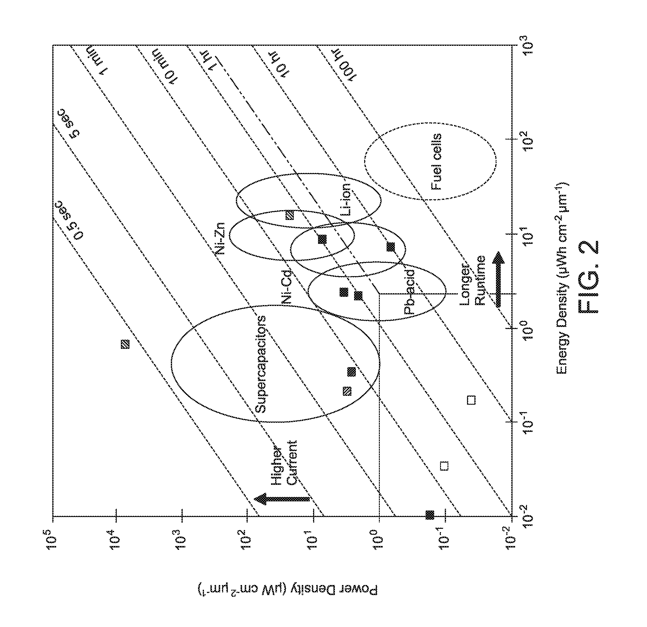
The specifications shown in FIG. 2 indicate that the four commercial microbatteries shown in FIG. 2 are poor candidates for a smart contact lens application.
Furthermore, the contents of these four commercial microbatteries are not biocompatible, and even the best packaging for these four commercial microbatteries is subject to dangerous failures from the flammable components which are contained under pressure.
Research into “biocompatible” microbatteries shows that, although their biocompatible components make them safer for use in the body, they tend to suffer from a performance output which is 10-20 times lower than the four commercial microbatteries shown in FIG. 2 (see E.F. Garay, “Biofluid-activated microbattery for disposable microsystems” Masters Thesis, University of Florida.
However, the test load on the biocompatible Al—AgO microbattery was 3 times higher, the active film of the biocompatible Al—AgO microbattery was ineffectively thin, and the duty cycle was a continuous drain on the microbattery—all factors that yield lower performance than could be made possible with improvements in material choices, battery thickness, and switching improvements between duty cycles.
In addition, powered electrical circuits typically experience another 20% current leakage loss per year.
Thus, nearly half of the battery power is typically lost during just a single year of storage.

Method used


Image

  • Point-of-use-activated microbattery and biocompatible electronic device incorporating the same
  • Point-of-use-activated microbattery and biocompatible electronic device incorporating the same
  • Point-of-use-activated microbattery and biocompatible electronic device incorporating the same

Examples


Embodiment Construction

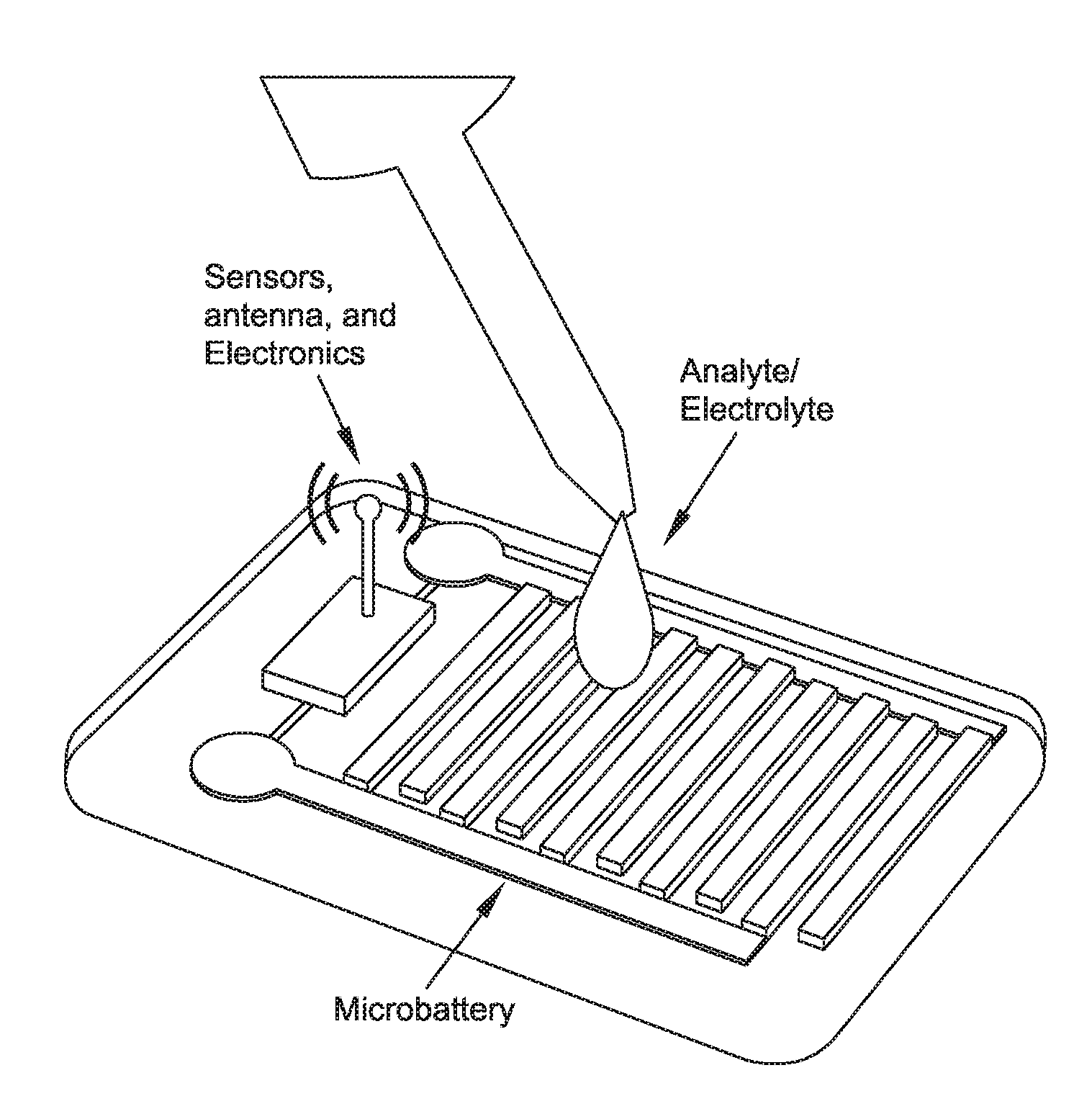
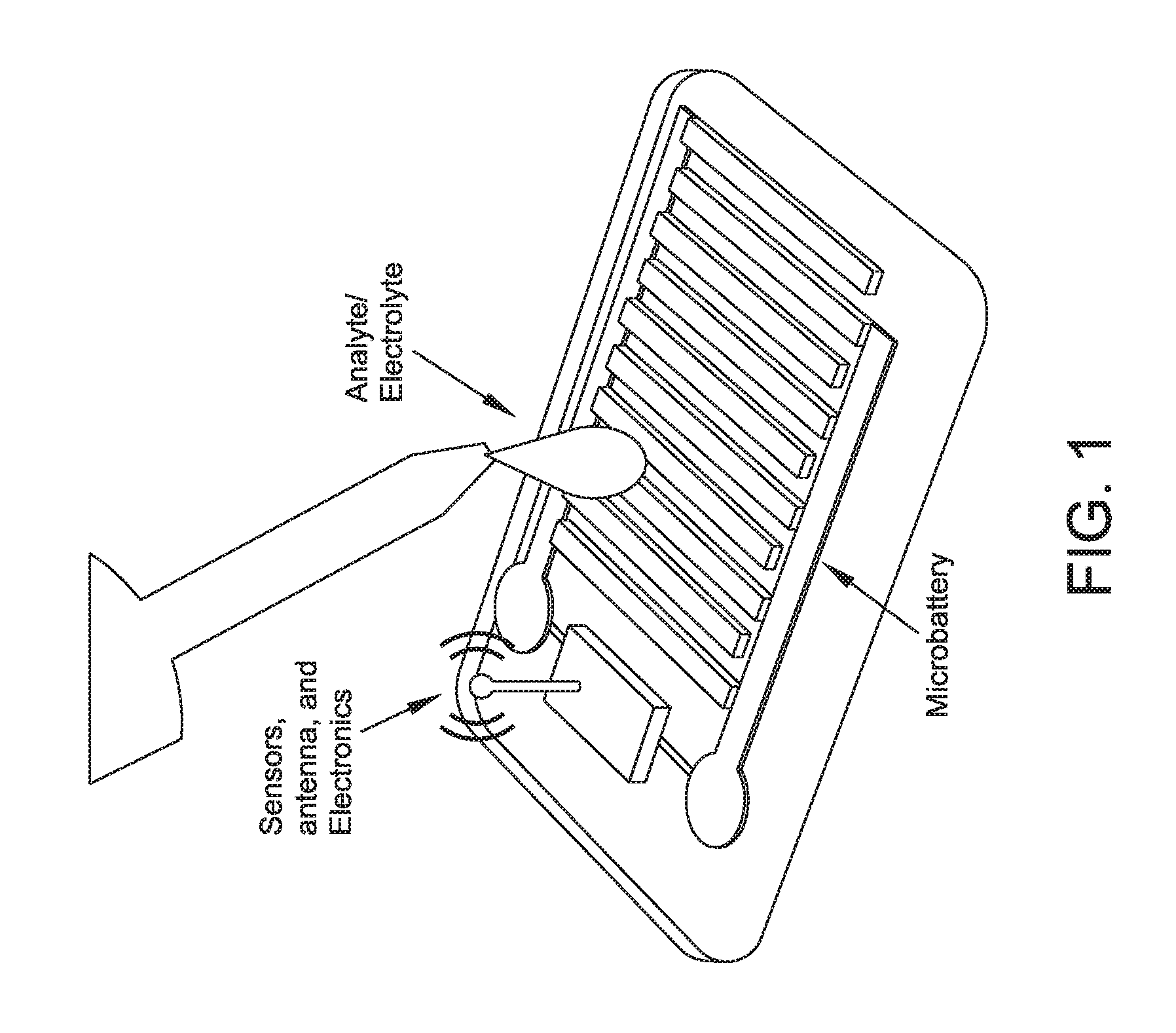
[0065]Looking next at FIG. 2A, the present invention comprises the provision and use of a novel biocompatible electronic device 5 (e.g., an LOC, a smart contact lens, etc.) that comprises a housing 10 having a sealed control electronics chamber 15 for containing control electronics 20 for controlling the operation of biocompatible electronic device 5 (e.g, for controlling operation of a sensor 22), and a sealed electrode chamber 25 for containing the electrodes 30, 35 of a microbattery for powering control electronics 20 contained in sealed control electronics chamber 15. Electrodes 30, 35 may comprise any biocompatible material consistent with the present invention (e.g., Al—AgO, magnesium-silver chloride electrodes, magnesium-copper chloride electrodes, etc.), and are connected to control electronics 20 contained in sealed control electronics chamber 15. Sealed electrode chamber 25 has an access port 40 that is sealed by a removable tab 45, such that upon removal of removable tab ...


PUM


Abstract

A biocompatible electronic device incorporating a point-of-use-activated microbattery, the biocompatible electronic device comprising: a housing; a sealed control electronics chamber formed within the housing; control electronics contained within the sealed control electronics chamber for controlling the operation of the biocompatible electronic device; a sealed electrode chamber formed within the housing; a plurality of electrodes contained within the sealed electrode chamber and connected to the control electronics; an access port formed within the housing for providing fluid access to the interior of the sealed electrode chamber; and a removable tab for selectively sealing the access port; such that, upon removal of the removable tab, a contacting fluid can contact the electrodes and act as an electrolyte for activating the microbattery, whereby to enable the microbattery to power the control electronics for the biocompatible electronic device.

Description

REFERENCE TO PENDING PRIOR PATENT APPLICATION[0001]This patent application claims benefit of pending prior U.S. Provisional Patent Application Ser. No. 62 / 135,756, filed Mar. 20, 2015 by Quantum Medical Innovations, LLC and Glen Jorgensen et al. for POINT-OF-USE-ACTIVATED MICROBATTERY FOR DISPOSABLE MEDICAL DEVICES (Attorney's Docket No. JORGEN-6 PROV), which patent application is hereby incorporated herein by reference.FIELD OF THE INVENTION[0002]This invention relates to biocompatible electronic devices in general, and more particularly to biocompatible electronic devices incorporating microbatteries for powering the same.BACKGROUND OF THE INVENTION[0003]Typical examples of applications in which the novel microbattery disclosed herein become an enabling technology include the newest generations of disposable, self-contained, Lab-On-a-Chip (LOC) diagnostic devices and the newest designs for disposable “smart” contact lenses (i.e., contact lenses which can change their optical prope...

Claims


Application Information

Patent Timeline
IPC IPC(8): H01M6/32G02C7/04G02C7/08H01M6/40H01M6/50
CPCH01M6/32H01M6/40H01M6/5088G02C2202/16G02C7/04H01M2220/30G02C7/083B29D11/00817
Inventor JORGENSEN, GLENREESER, STEVE
Owner QUANTUM MEDICAL INNOVATIONS LLC
Learn More