Retroreflective light field display

a retroreflective light field and display technology, applied in optics, instruments, electrical equipment, etc., can solve problems such as and difficulty in adjusting the brightness of the display head

Active Publication Date: 2016-09-22
TILT FIVE INC
View PDF7 Cites 21 Cited by
  • Summary
  • Abstract
  • Description
  • Claims
  • Application Information

AI Technical Summary

Problems solved by technology

However, conventional approaches to light field displays for augmented reality (AR) and virtual reality (VR) suffer from various problems and drawbacks.
These include problems with brightness and other issues.
Additionally, some of the approaches are more complicated and expensive than desired.

Method used


Image

  • Retroreflective light field display
  • Retroreflective light field display
  • Retroreflective light field display

Examples


Embodiment Construction

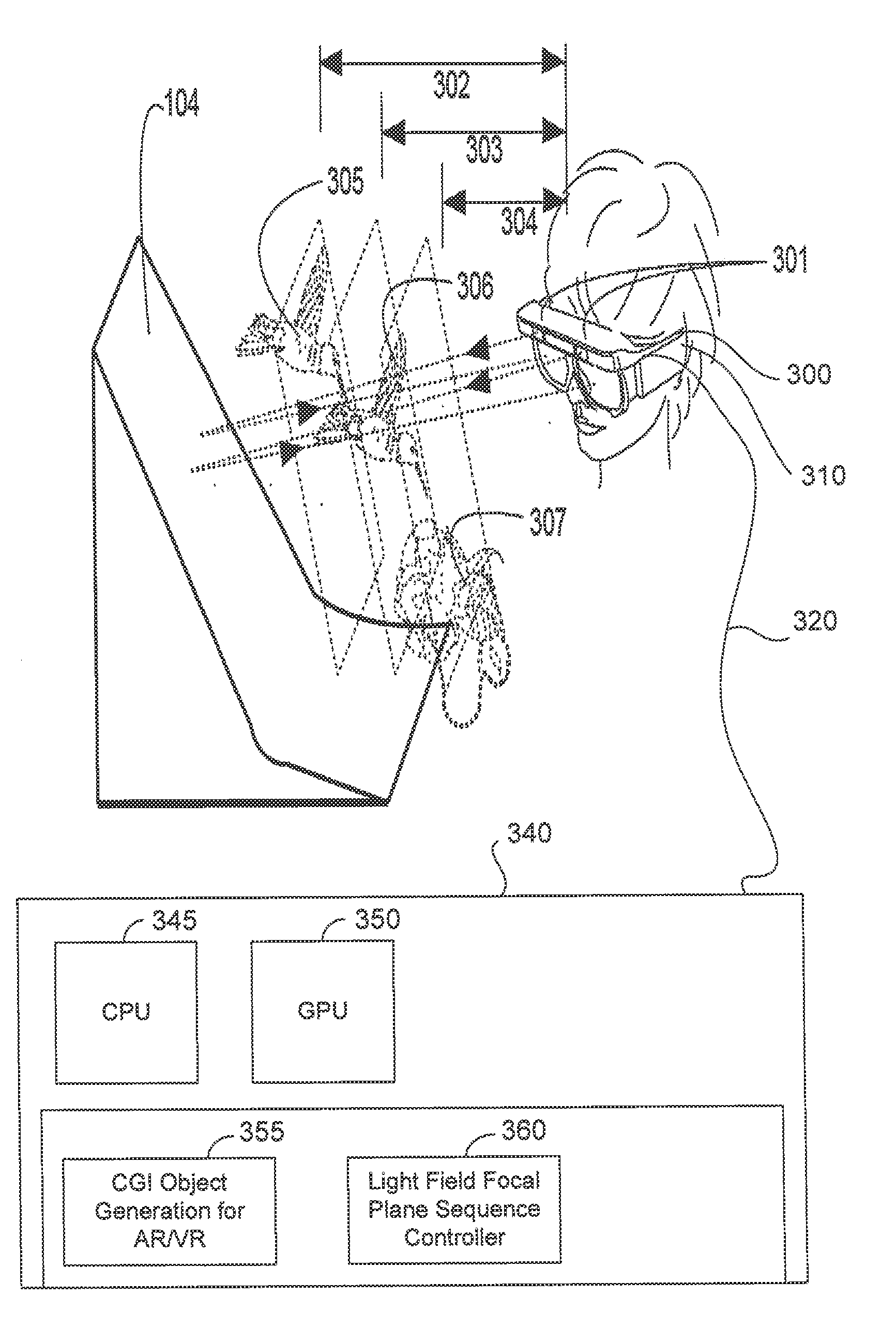
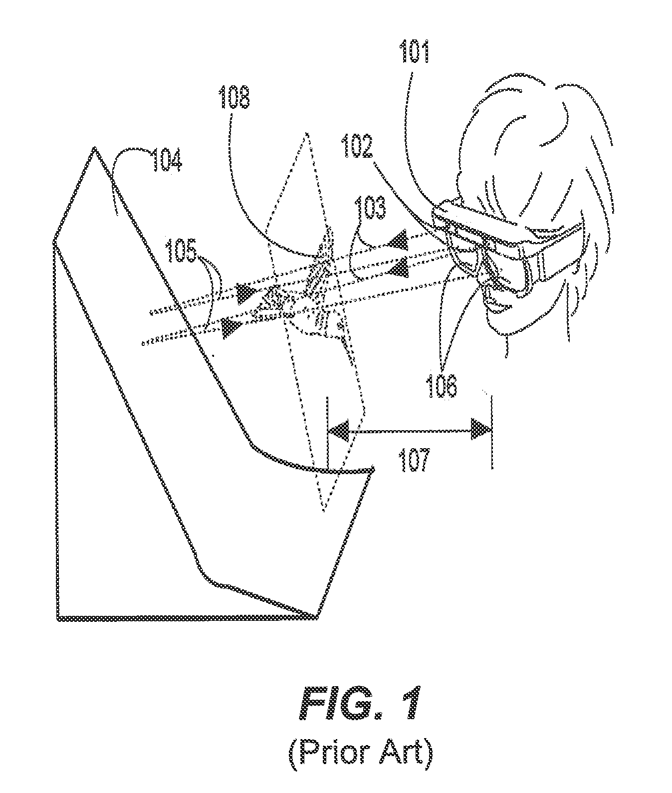
[0026]A PHMD system (such as described by Ellsworth US 2014 / 340,424) is shown in FIG. 1. In this system a head mounted frame 101 houses a pair of image projectors 102 that send projected rays 103 to be reflected by retroreflective screen 104. The returned image rays 105 are segregated to be seen by corresponding eyes by means of lenses 106, thus providing stereopsis. The retroreflective screen 104 is a quasi-phase conjugate screen. The phase conjugate optic property of retroreflective screen 104 causes the eyes of the user to accommodate to the distance 107 set by the projection focus of projectors 102 even though the distance to screen 104 may be more or less than the projection focal distance (FIG. 1 shows only a shorter distance for 107. A longer distance, not shown, would make the image 108 seem to be behind the screen 104, and shining through it).

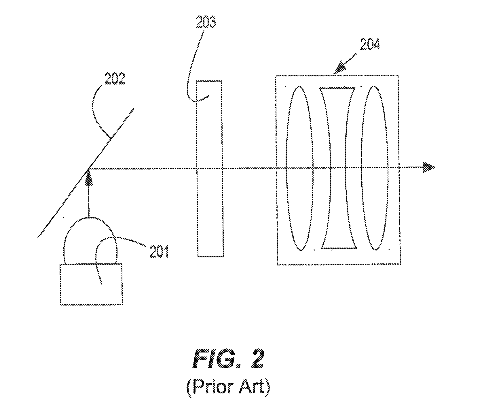
[0027]In FIG. 2, a simplified optical path of a typical prior art image projector of a PHMD of FIG. 1 is shown in detail. In this ima...


PUM


Abstract

A projected head mounted display system is disclosed that projects images onto a retroreflective screen, which are then reflected back for view by a user. The projected head mounted display system displays computer generated images at multiple focal distances to simulate a light field so as to match eye accommodation to vergence.

Description

CROSS REFERENCE TO RELATED APPLICATIONS[0001]The present application claims the benefit of U.S. provisional application 62 / 135,905 “Retroreflective Light Field Display” the contents of which are hereby incorporated by reference.FIELD OF THE INVENTION[0002]The current invention is related to the field of three dimensional displays of computer generated images, and specifically projected head mounted displays. More particularly, embodiments of the present invention are directed to a head mounted retroreflective light field display.BACKGROUND OF THE INVENTION[0003]A light field is a representation of light. To produce a light field, views are obtained for a collection of viewpoints. Thus, a light field contains a number of different images. The number of images that is required depends on the application.[0004]Light field displays are used for the presentation of images to the eyes of the user that comprise a plurality of planes of focus such that the human viewer can see different ima...

Claims


Application Information

Patent Timeline
Patent Type & Authority Applications(United States)
IPC IPC(8): H04N13/04H04N13/00
CPCH04N13/044H04N13/0468H04N13/0459G02B2027/0127H04N13/0022H04N13/0497H04N13/0427
Inventor ELLSWORTH, JERI J.CLEMENTS, KEN
Owner TILT FIVE INC
Why Eureka
Try Eureka