Parallel axis stereoscopic camera

a stereoscopic camera and parallel axis technology, applied in the field of parallel axis stereoscopic cameras, can solve the problems of inability to adjust the disparity amount according, observer fatigue, and so on, and achieve the effects of preventing image loss, minimizing image distortion and time delay, and preventing image loss

Inactive Publication Date: 2013-04-18
ASIC BANK CO LTD
View PDF3 Cites 9 Cited by
  • Summary
  • Abstract
  • Description
  • Claims
  • Application Information

AI Technical Summary

Benefits of technology

[0037]According to the present invention, there is an effect to provide a parallel axis stereoscopic camera with electronic vergence control function and electronic camera alignment function that can prevent image loss due to the mechanical alignment error between left and right cameras.
[0038]Also, there is an effect to provide a parallel axis stereoscopic camera with electronic vergence control function and electronic camera alignment function that can prevent image loss in the course of vergence control.
[0039]Further, there is an effect to provide a parallel axis stereosc

Problems solved by technology

In the case an observer views a stereoscopic image obtained from a camera not having the vergence control function, the disparity amount is so great that the observer feels seriously fatigued.
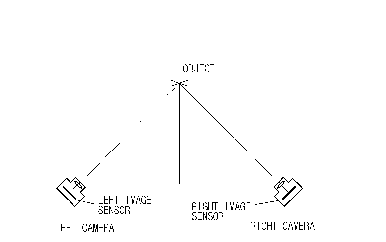
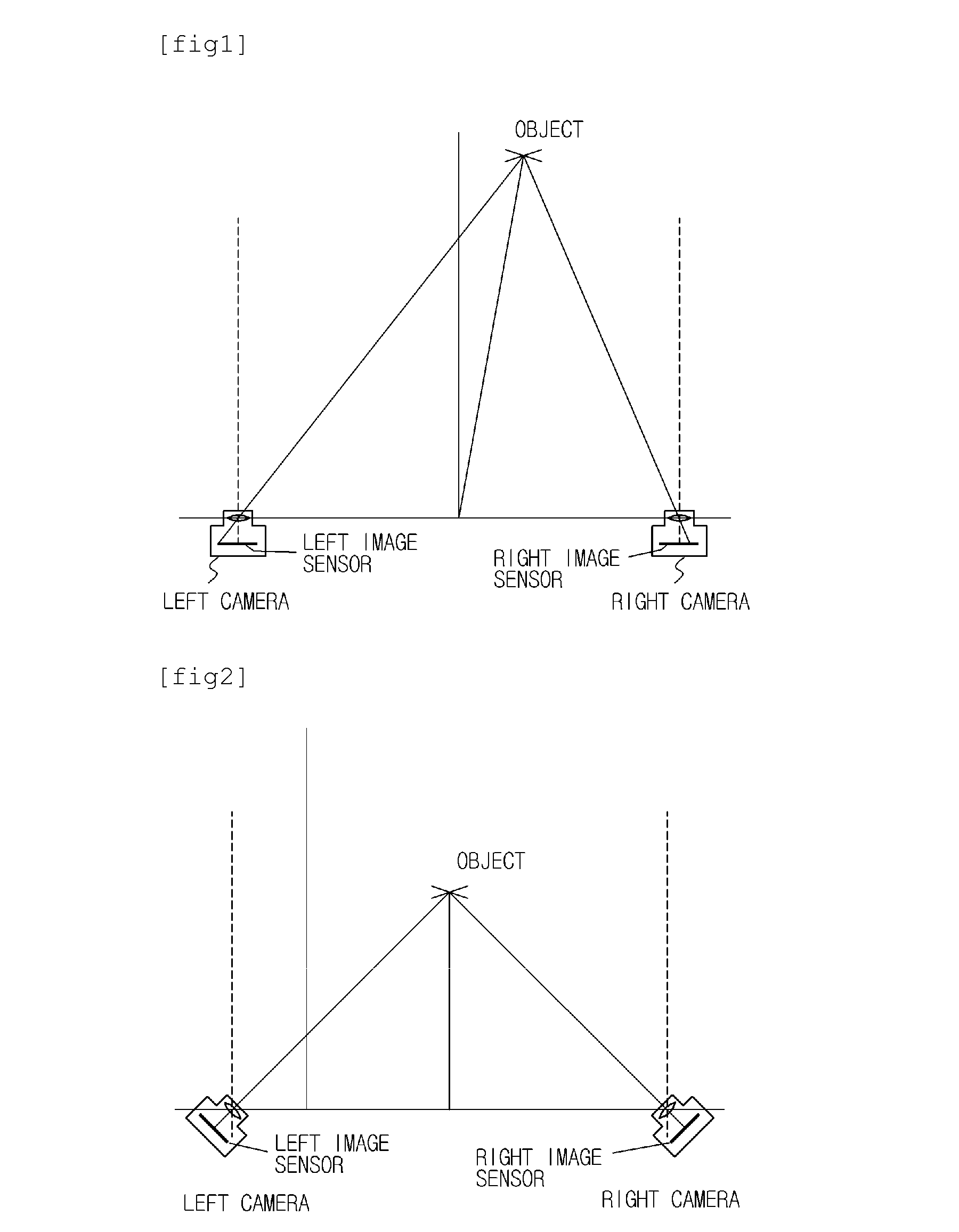
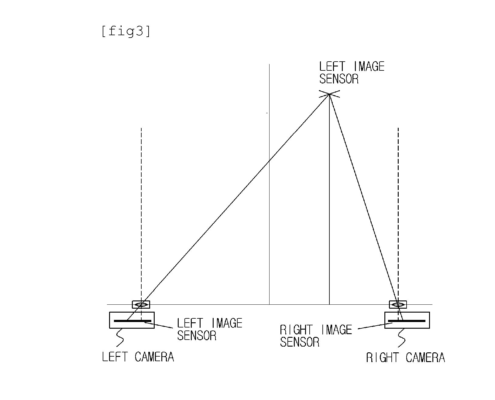
However, since the parallel axis stereoscopic camera does not have the vergence control function, it has a problem in that the disparity amount cannot be adjusted according to a change in distance from an object.
However, in the case of the toed-in type, since the vergence is adjusted by crossing the image sensors, the change in interval between the image sensors is so much that serious distortion is generated in reproduction of a stereoscopic image.
Also, since the vergence control has to be performed by rotation of the optical axis of the camera, the toed-in stereoscopic camera has a difficulty in miniaturization.
According to the type of controlling the vergence by parallel movement of the image sensors, the horizontal moving axis stereoscopic

Method used


Image

  • Parallel axis stereoscopic camera
  • Parallel axis stereoscopic camera
  • Parallel axis stereoscopic camera

Examples


second embodiment

[0094]FIG. 12 is a block diagram of a parallel axis stereoscopic camera according to the present invention.

[0095]Referring to FIG. 12, a parallel axis stereoscopic camera according to a second embodiment of the present invention includes: a camera unit 10 which includes a left image sensor 12 and a right image sensor 14 each of which has a higher resolution than an output image, the camera unit outputting RGB data having the same resolution as the output image; a vergence controller 20 which performs an electronic control for eliminating a binocular disparity of an object by changing a read-out starting point in the horizontal direction, of at least one of the left and right image sensors 12 and 14; a stereoscopic RGB data synthesizer 42 which synthesizes left RGB data outputted from the left image sensor 12 with right RGF data outputted from the right image sensor 14 to produce stereoscopic RGB data under the control of the vergence controller 20; and an image processor 32 which pr...

third embodiment

[0099]FIG. 13 is a block diagram of a parallel axis stereoscopic camera according to the present invention.

[0100]Referring to FIG. 13, a parallel axis stereoscopic camera according to a third embodiment of the present invention includes: a camera unit 10 which includes a left image sensor 12 and a right image sensor 14 each of which has a higher resolution than an output image, the camera unit outputting RGB data having the same resolution as the output image; a vergence controller 20 which performs an electronic control for eliminating a binocular disparity of an object by changing a read-out starting point in the horizontal direction, of at least one of the left and right image sensors 12 and 14; a stereoscopic image processor 33 which processes an image of left RGB data outputted from the left image sensor 12 to generate a left luminance / chrominance signal, processes an image of right RGB data outputted from the right image sensor 14 to generate a right luminance / chrominance sign...

fourth embodiment

[0103]FIG. 14 is a block diagram of a parallel axis stereoscopic camera according to the present invention.

[0104]Referring to FIG. 14, a parallel axis stereoscopic camera according to a fourth embodiment of the present invention includes: a camera unit 10 which includes a left image sensor 12 and a right image sensor 14 each of which has a higher resolution than an output image, the camera unit 10 outputting left luminance / chrominance signal and right luminance / chrominance signal having the same resolution as the output image; a vergence controller 20 which performs an electronic control for eliminating a binocular disparity of an object by changing a read-out starting point in the horizontal direction, of at least one of the left and right image sensors 12 and 14; and a stereoscopic image synthesizer 44 which synthesizes the left luminance / chrominance signal and the right luminance / chrominance signal to produce a stereoscopic image.

[0105]Compared with other embodiments, the fourth ...


PUM


Abstract

A parallel axis stereoscopic camera comprising: a camera unit which includes left and right image sensors each of which has a higher resolution than an output image, the camera unit outputting RGB data having the same resolution as the output image; a vergence controller which performs an electronic control for eliminating a binocular disparity of an object by changing a read-out starting point in the horizontal direction, of at least one of the left and right image sensors; an image processor including a left image processing unit which processes an image of left RGB data to output a left luminance/chrominance signal and a right image processing unit which processes an image of right RGB data to outputs a right luminance/chrominance signal under the control of the vergence controller; and a stereoscopic image synthesizer which synthesizes the left and right luminance/chrominance signals to produce a stereoscopic image.

Description

TECHNICAL FIELD[0001]The present invention relates to a parallel axis stereoscopic camera. More particularly, the present invention relates to a parallel axis stereoscopic camera with vergence control function and electronic camera alignment function, which allows the parallel axis stereoscopic camera to electronically control the vergence, and which can minimize image loss generated due to the electronic vergence control error and the alignment error between a left hand side camera and a right hand side camera.BACKGROUND ART[0002]In general, a stereoscopic camera obtains left and right images by using two cameras like human eyes, and allows an observer to feel stereoscopic effect by the parallax of the left and right images.[0003]Parallax or binocular disparity refers to the difference in image direction of an object seen from two viewpoints, and allows the image of the object to be formed at different locations on image capturing surfaces of image sensors equipped in two cameras o...

Claims


Application Information

Patent Timeline
IPC IPC(8): H04N13/02H04N13/239
CPCG03B35/08H04N13/0239H04N2013/0081H04N13/0257H04N13/0296H04N13/0246H04N13/246H04N13/257H04N13/296H04N13/239
Inventor KANG, HEE MINPARK, EUN HWA
Owner ASIC BANK CO LTD
Why Eureka
Try Eureka