Interactive projector and method of controlling interactive projector

Active Publication Date: 2016-09-29
SEIKO EPSON CORP
View PDF5 Cites 4 Cited by
  • Summary
  • Abstract
  • Description
  • Claims
  • Application Information

AI Technical Summary

Benefits of technology

This patent describes an interactive projector that uses cameras to detect the first and second coordinate positions of a pointing element on a projected screen. By checking if these positions roughly match, the system can easily determine if the pointing element has made contact with the screen. This makes it easy to detect and respond to user interactions on the screen, improving the overall experience of the user. The system also takes into account the fact that if the pointing element touches the screen, it will naturally move around the screen, making it easy to determine its exact location on the screen.

Problems solved by technology

However, there has been a problem that the projector, which detects the three-dimensional position of the tip of the pointing element using a plurality of cameras in order to calculate the distance between the tip of the pointing element and the screen, takes time to calculate the three-dimensional position, or fails to obtain sufficient detection accuracy.

Method used


Image

  • Interactive projector and method of controlling interactive projector
  • Interactive projector and method of controlling interactive projector
  • Interactive projector and method of controlling interactive projector

Examples


modified example 1

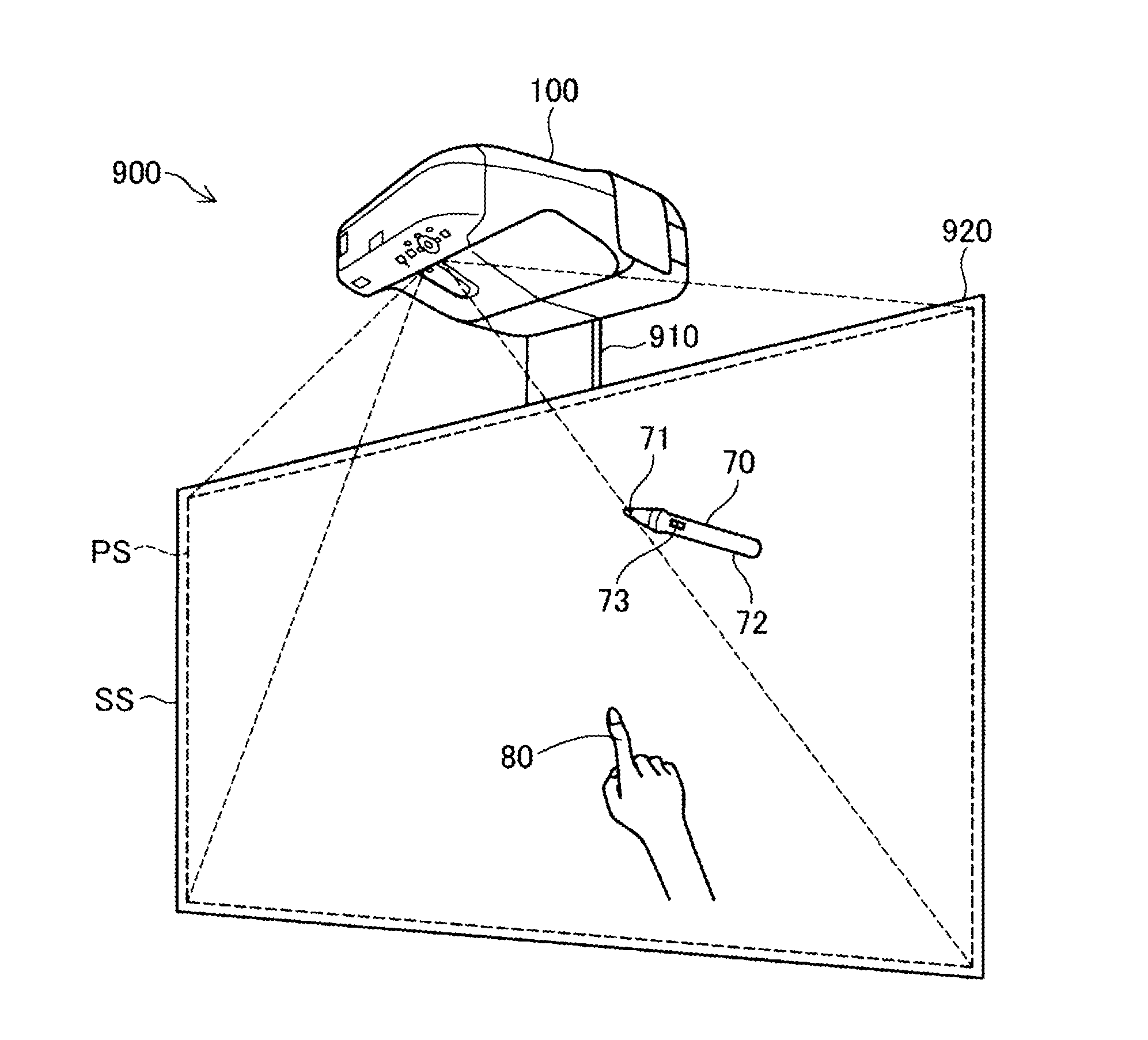
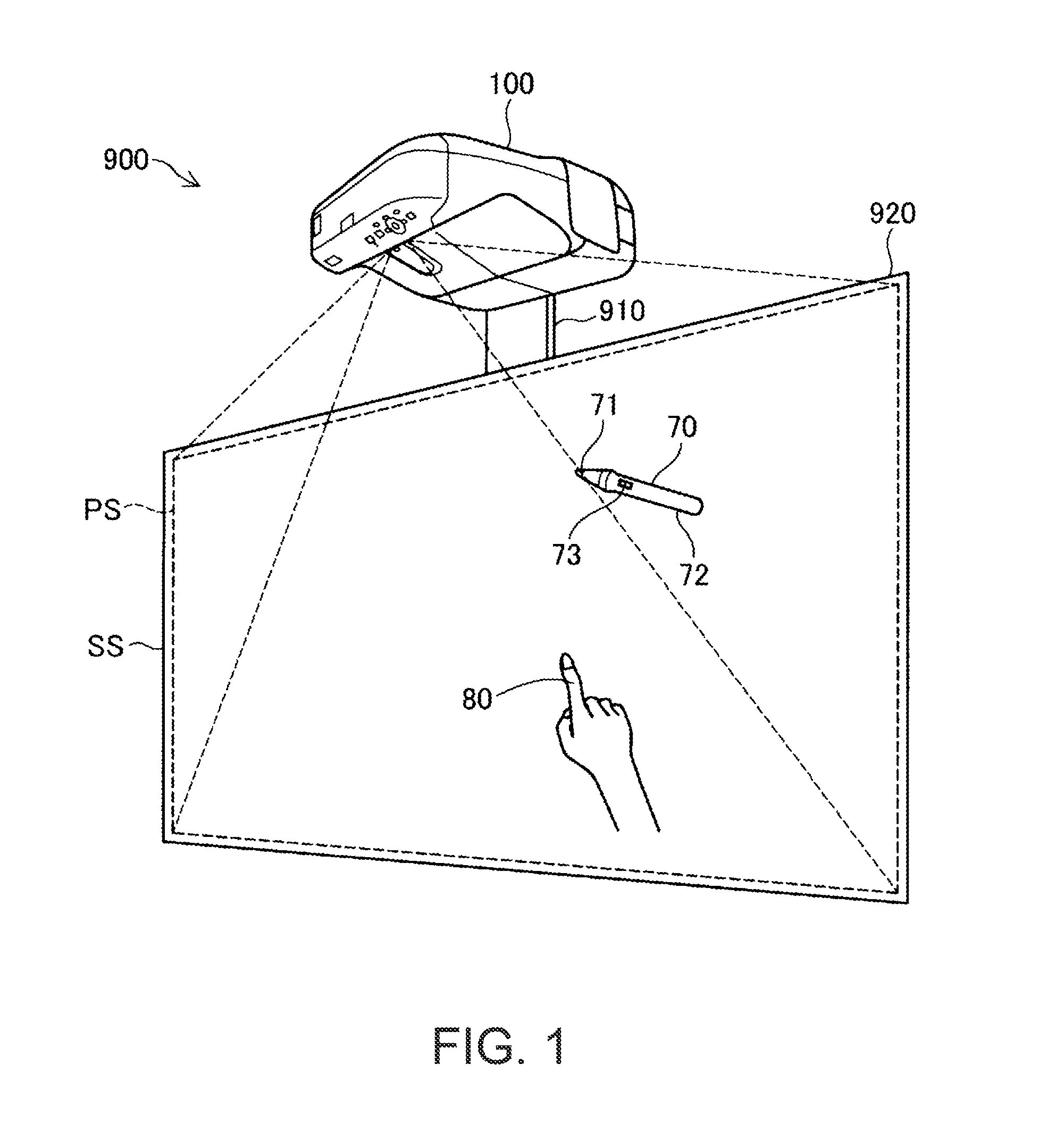
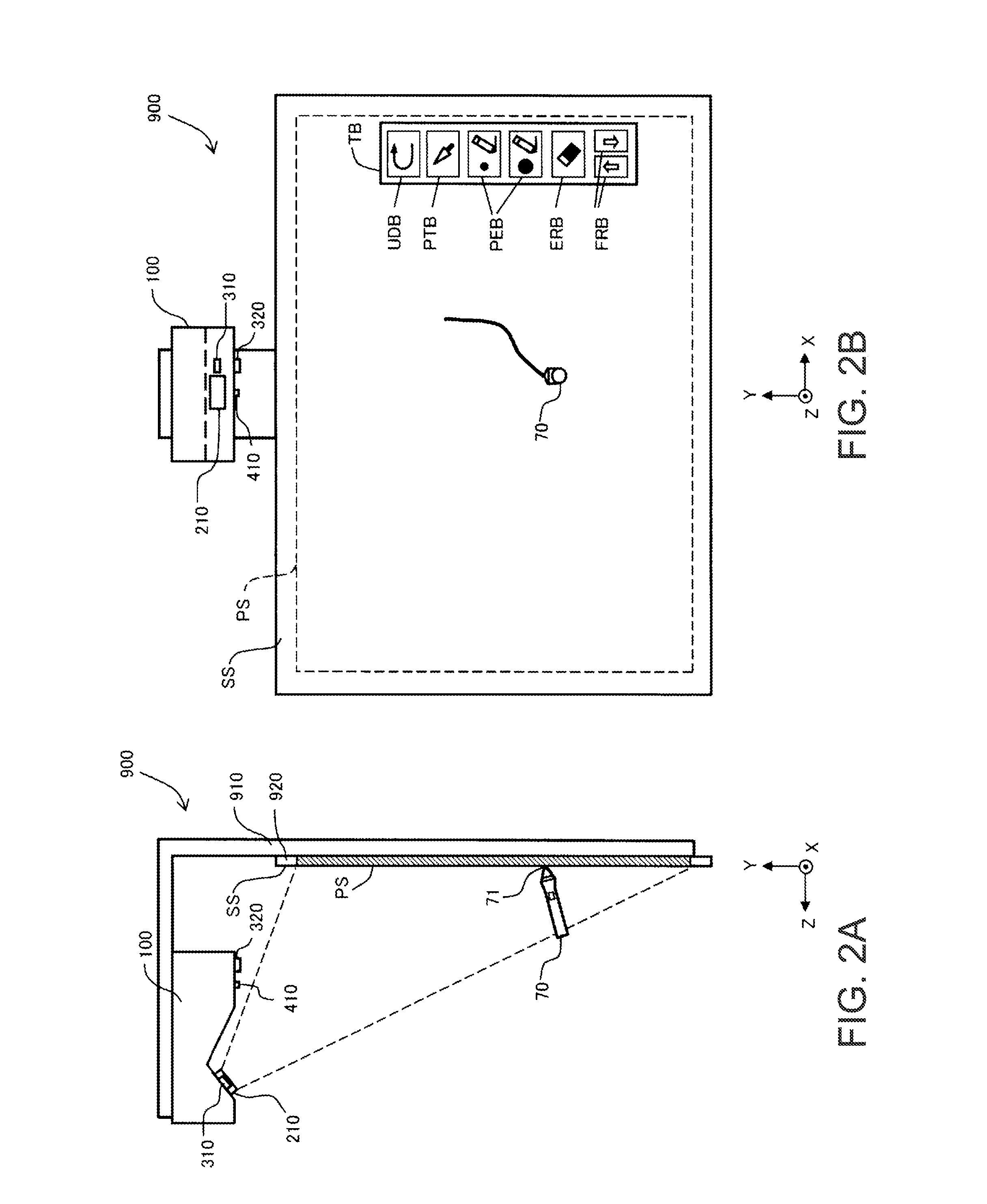
[0064]Although in the embodiment described above, it is assumed that the imaging section 300 includes the two cameras 310, 320, the imaging section 300 can also include three or more cameras. In the latter case, the determination on whether or not the tip portion 81 of the non-light-emitting pointing element 80 has contact with the screen surface SS can be performed based on m (m is an integer equal to or greater than 3) images taken by the m cameras. For example, it is possible to obtain the two-dimensional position coordinate (X81, Y81) of the tip portion 81 in the projected screen PS using mC2 combinations obtained by arbitrarily selecting two images out of the m images, and then determine whether or not the tip portion 81 of the non-light-emitting pointing element 80 has contact with the screen surface SS using the average value of the distances between the two-dimensional position coordinates. By adopting this configuration, the detection accuracy of the contact can further be ...

modified example 2

[0065]Although in the embodiments described above, it is assumed that the interactive projection system 900 can act in the whiteboard mode and the PC interactive mode, the system can also be configured so as to act in either one of the modes. Further, it is also possible for the interactive projection system 900 to be configured so as to act only in other modes than these two modes, or further to be configured so as to be able to act in a plurality of modes including these two modes.

modified example 3

[0066]Although in the embodiments described above it is assumed that the irradiating detection light IDL, the reflected detection light RDL, the device signal light ASL, and the pointing element signal light PSL shown in FIG. 3 are all the near infrared light, it is also possible to assume that some or all of these types of light are light other than the near infrared light.


PUM


Abstract

An interactive projector includes a projection section, a plurality of cameras including a first camera and a second camera, a position detection section adapted to detect a first coordinate position of the pointing element on the projected screen based on a first taken image including the pointing element taken by the first camera, and detect a second coordinate position of the pointing element on the projected screen based on a second taken image including the pointing element taken by the second camera, and a contact detection section adapted to detect contact of the pointing element with the projected screen based on the first coordinate position and the second coordinate position, and the contact detection section detects the contact of the pointing element with the projected screen in a case in which the first coordinate position and the second coordinate position coincide with each other within an allowable tolerance.

Description

[0001]The entire disclosure of Japanese Patent Application No. 2015-065627, filed Mar. 27, 2015 is expressly incorporated by reference herein.BACKGROUND[0002]1. Technical Field[0003]The present invention relates to an interactive projector capable of receiving an instruction of the user to a projected screen with a pointing element, and a method of controlling the projector.[0004]2. Related Art[0005]JP-A-2012-150636 and JP-T-2008-520034 disclose a projection display device (projector) capable of projecting a projected screen on a screen, and at the same time taking an image, which includes an object such as a finger or a light emitting pen, with a camera to detect the position of the object using the taken image. An object such as a finger is used as a pointing element for making an instruction to the projection image. In other words, when the tip of the object has contact with the screen, the projector recognizes that a predetermined instruction such as drawing is input with respec...

Claims


Application Information

Patent Timeline
IPC IPC(8): G06F3/038H04N9/31G06F3/00
CPCG06F3/038H04N9/31G06F3/005H04N9/3185H04N9/3194G06F3/0425G06F3/03545
Inventor MOUSSAKHANI, BABAK
Owner SEIKO EPSON CORP
Why Eureka
Try Eureka