Antenna device and communication terminal apparatus
a technology of communication terminal and antenna device, which is applied in the structure of loop antenna with ferromagnetic core, radiating element, instruments, etc., can solve the problems of affecting the miniaturization of the communication terminal apparatus, the size of the coil antenna, etc., and achieve the effect of small area and small communication terminal apparatus
- Summary
- Abstract
- Description
- Claims
- Application Information
AI Technical Summary
Benefits of technology
Problems solved by technology
Method used
Image
Examples
first embodiment
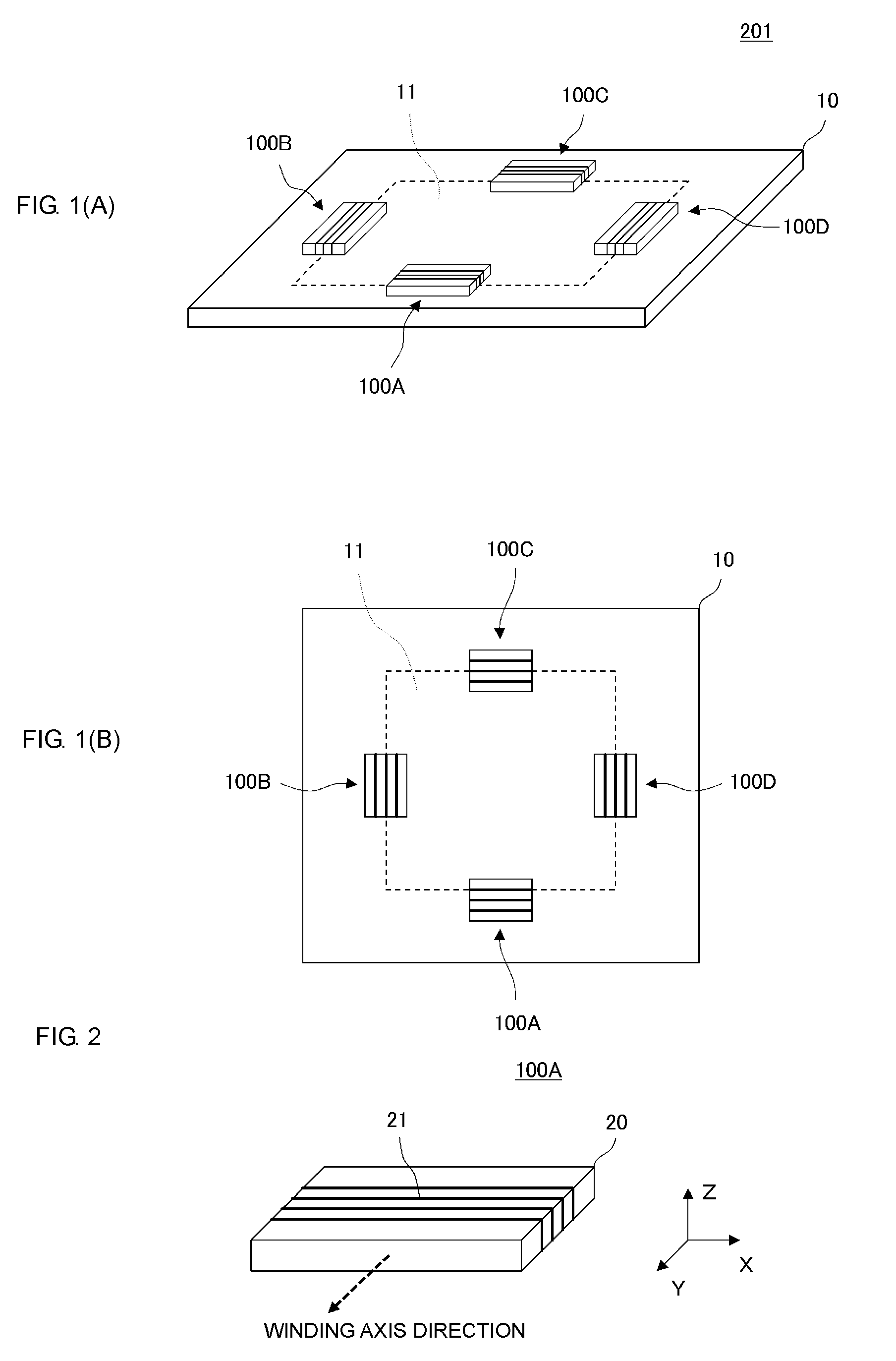
[0041]FIG. 1(A) is a perspective view of an antenna device 201 according to a first embodiment and FIG. 1(B) is a plan view thereof.
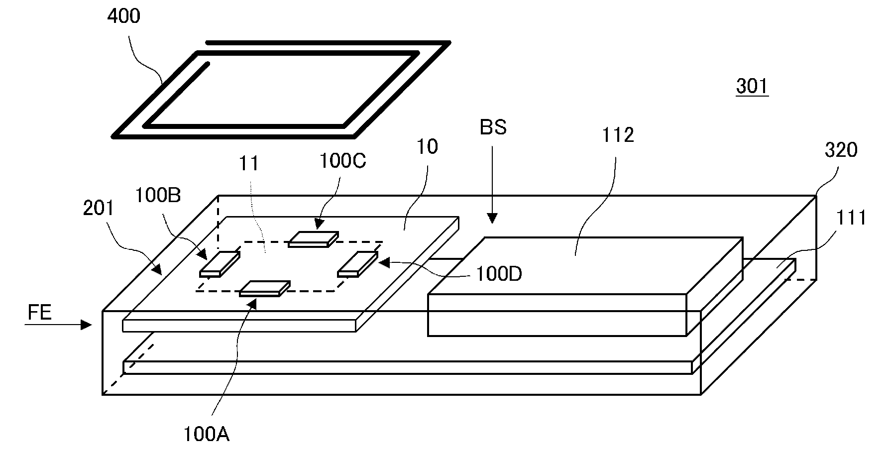
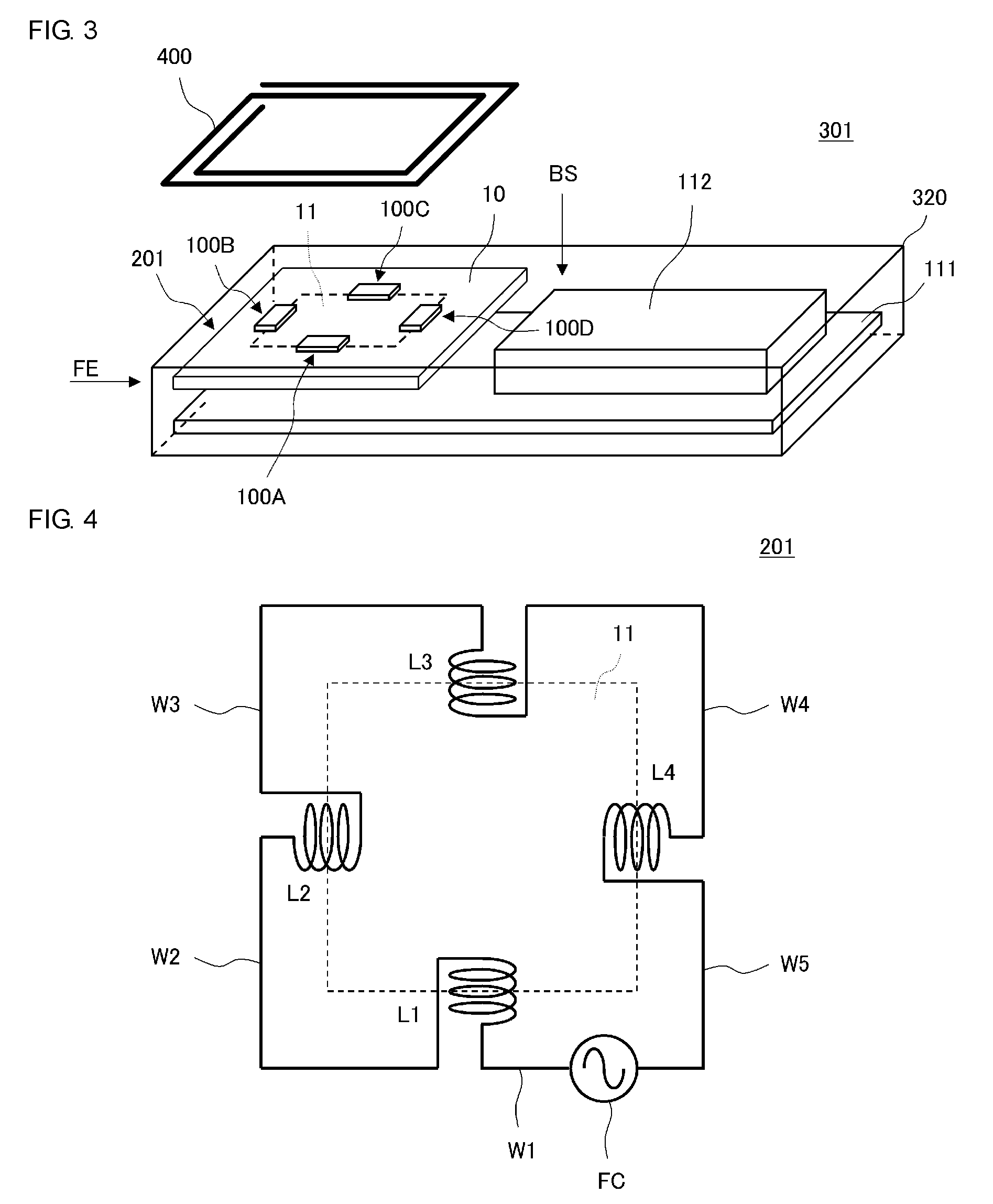
[0042]As illustrated in FIGS. 1(A) and 1(B), the antenna device 201 includes four coil antennas 100A, 100B, 100C, and 100D. Each of the coil antennas 100A, 100B, 100C, and 100D has a structure in which a coil conductor is wound around a magnetic core, as described below.
[0043]The antenna device 201 further includes a planar conductor 11 including a surface parallel to the winding axis direction of each of the coil conductors. The planar conductor 11 is disposed on a base 10. The coil antennas 100A, 100B, 100C, and 100D are mounted on the base 10. Each of the coil antennas 100A, 100B, 100C, and 100D is arranged such that a coil opening of the coil conductor is adjacent (close) to the edge end portion of the planar conductor 11.
[0044]The planar conductor is made of metallic foil of copper, silver, aluminum, or other metal and is disposed on the base made ...
second embodiment
[0063]FIG. 6 illustrates a connection relation between the coil antennas of an antenna device 202 according to a second embodiment and a connection relation with a feed circuit. The coil conductors of the coil antennas are denoted as the coils L1 to L4 here. The configuration of each coil antenna is substantially the same as in the first embodiment.
[0064]As illustrated in FIG. 6, in the antenna device 202 according to the present embodiment, each of the coils L1 to L4 is connected to the feed circuit FC. That is, the coil conductors of the coil antennas are connected to the feed circuit FC such that they are in parallel to each other. More specifically, a first input / output port of the feed circuit FC is connected to a first end of the coil L1 through wiring W1, and a second end of the coil L1 is connected to a second input / output port of the feed circuit FC through wiring W2. Similarly, the first input / output port of the feed circuit FC is connected to a first end of the coil L2 th...
third embodiment
[0068]FIG. 7(A) is a perspective view of an antenna device 203 according to a third embodiment and FIG. 7(B) is a plan view thereof.
[0069]As illustrated in FIGS. 7(A) and 7(B), the antenna device 203 according to the third embodiment is the one in which the first coil antenna 100A is arranged in the vicinity of one of the two long sides of the rectangular planar conductor 11 and the second coil antenna 100B and the third coil antenna 100C are arranged in the vicinities of the two short sides. In this manner, the arrangement in which a plurality of coil antennas are arranged such that the coil openings thereof face each other in the direction of the long sides of the planar conductor 11 enables a magnetic flux to be efficiently guided to the coil antennas.
[0070]As illustrated in FIGS. 7(A) and 7(B), the arrangement in which the plurality of coil antennas 100A, 100B, and 100C are asymmetric with respect to the center of the planar conductor 11 enables the antenna device 203 to have di...
PUM
 Abstract
Description
Claims
Application Information
 - R&D
- Intellectual Property
- Life Sciences
- Materials
- Tech Scout
- Unparalleled Data Quality
- Higher Quality Content
- 60% Fewer Hallucinations
Browse by: Latest US Patents, China's latest patents, Technical Efficacy Thesaurus, Application Domain, Technology Topic, Popular Technical Reports.
© 2025 PatSnap. All rights reserved.Legal|Privacy policy|Modern Slavery Act Transparency Statement|Sitemap|About US| Contact US: help@patsnap.com


