Resonator, filter, and communication unit
a filter and communication unit technology, applied in the direction of waveguide devices, resonators, basic electric elements, etc., can solve the problems of difficult to obtain a predetermined resonant frequency with high precision, and the line width cannot be extremely narrow, so as to achieve the effect of small communication apparatus and size of high-frequency circuit parts
- Summary
- Abstract
- Description
- Claims
- Application Information
AI Technical Summary
Benefits of technology
Problems solved by technology
Method used
Image
Examples
first embodiment
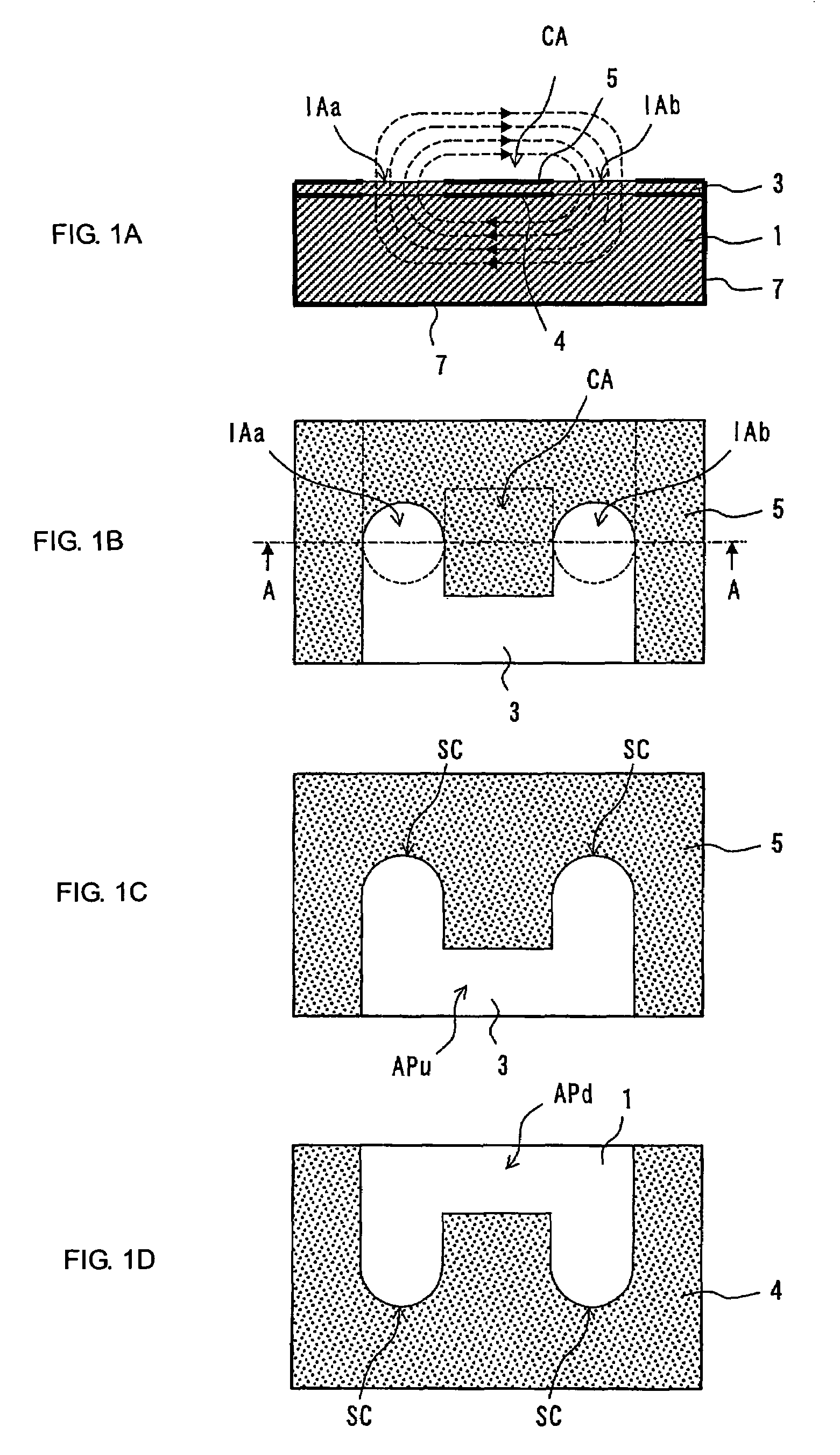
[0027]A resonator is discussed below with reference to FIG. 1.
[0028]FIG. 1B, is a top view illustrating the resonator, FIG. 1A is a sectional view taken along line A-A in FIG. 1B, FIG. 1C illustrates the pattern of a conductor layer disposed on the top surface, and FIG. 1D illustrates the pattern of a conductor layer pattern disposed as the bottom layer.
[0029]On the top surface of a rectangular dielectric substrate 1, a conductor layer 4 having the pattern shown in FIG. 1D is formed. A dielectric layer 3 is disposed on the entire top surface of the dielectric substrate 1 on which the conductor layer 4 is formed, and a conductor layer 5 having the pattern shown in FIG. 1C is formed on the surface of the dielectric layer 3. (See FIG. 1A) With this configuration, a structure in which the conductor layers 4 and 5 are laminated in the thickness direction with the dielectric layer 3 therebetween is formed. In the state in which the conductor layers 4 and 5 are laminated with the dielectr...
second embodiment
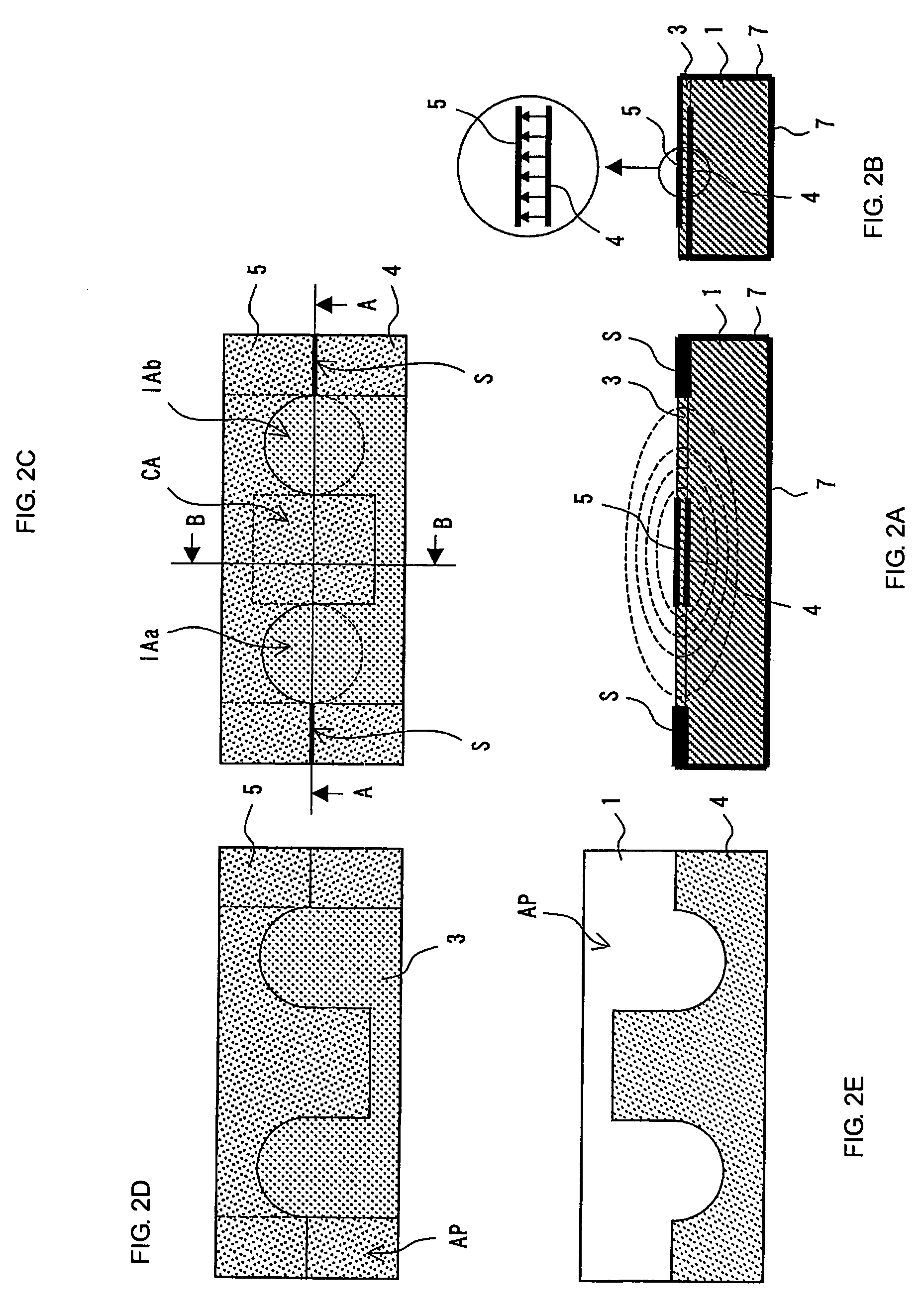
[0038]FIGS. 2A to 2E illustrates the configuration of a resonator according to a FIG. 2C, is a top view illustrating the resonator, FIG. 2A is a sectional view taken along line A-A in FIG. 2C, and FIG. 2B is a sectional view taken along line B-B in FIG. 2C. FIG. 2D, illustrates the pattern of a conductor layer 5 as the upper layer, and FIG. 2E illustrates the pattern of a conductor layer 4 as the lower layer. Unlike the resonator shown in FIGS. 1A to 1D, the conductor layers 4 and 5 in this embodiment are partially electrically connected to each other by interlayer short-circuit portions S on the top surface of the dielectric substrate 1. The dielectric layer 3 is not present in the interlayer short-circuit portions S. According to this structure, the conductor layers 4 and 5 are short-circuited more reliably in the vicinities of the conductor openings by the interlayer short-circuit portions S compared to the structure in which the conductor layers 4 and 5 are short-circuited only...
third embodiment
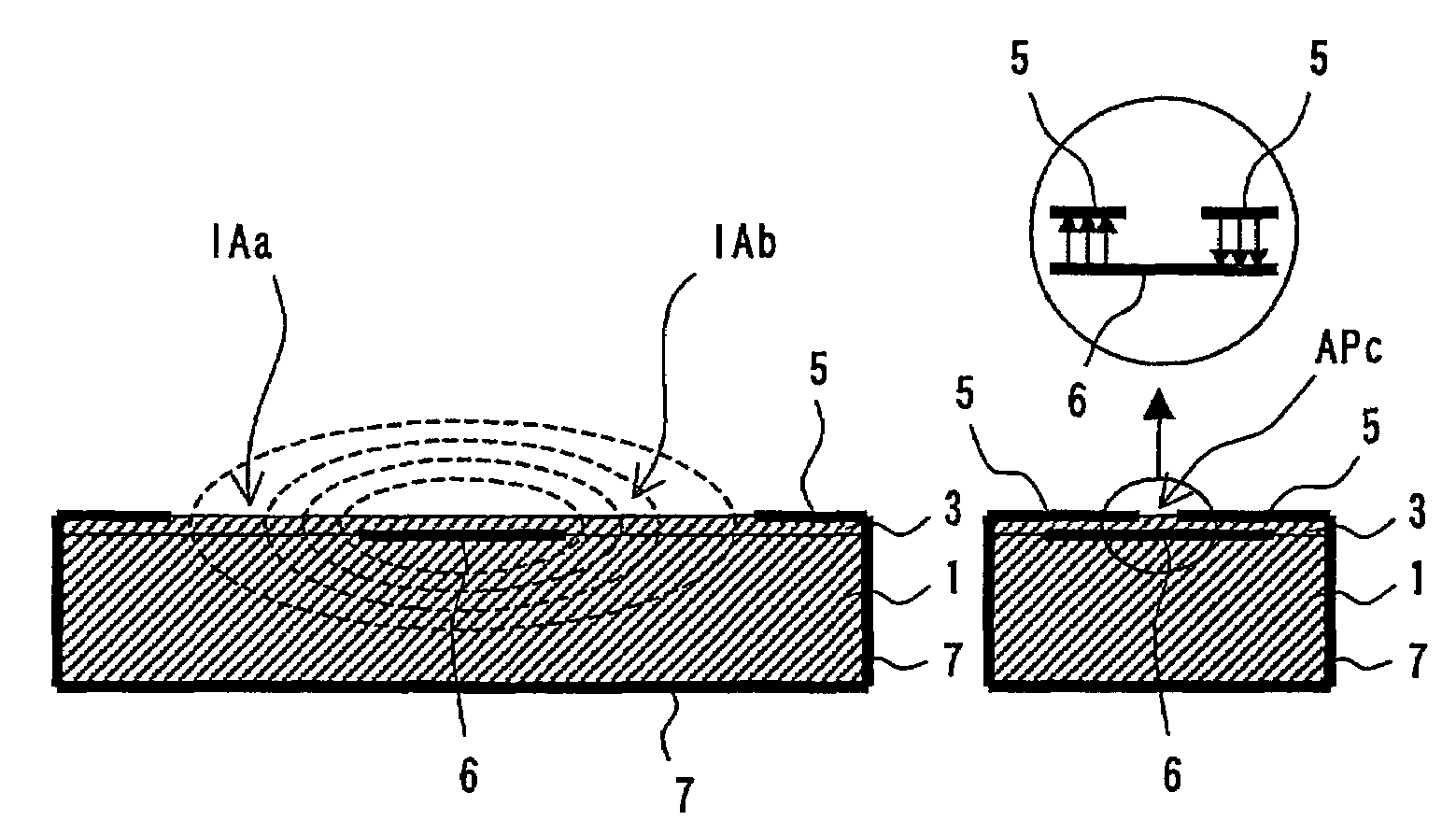
[0039]FIGS. 3A to 3E illustrates the configuration of a resonator according to a FIG. 3C, is a top view illustrating the resonator, FIG. 3A is a sectional view taken along line A-A in FIG. 3C, and FIG. 3B is a sectional view taken along line B-B in FIG. 3C. FIG. 3D, illustrates the pattern of a conducive layer 5 as the upper layer, and FIG. 3E illustrates the pattern of a conductor layer 6 as the lower layer.
[0040]The conductor layer 6 is formed in a predetermined portion on the top surface of the dielectric substrate 1. The conductor layer 5 having the pattern shown in FIG. 3D is formed on the top surface of the conductor layer 6 with the dielectric layer 3 therebetween. The conductor opening of the conductor layer 5 is formed in a dumbbell shape in which generally circular conductor openings APa and APb are formed at both ends and a slot conductor opening APc having a predetermined width is interposed between the conductor openings APa and APb. The conductor layer 6 is formed in ...
PUM
 Abstract
Description
Claims
Application Information
 - R&D
- Intellectual Property
- Life Sciences
- Materials
- Tech Scout
- Unparalleled Data Quality
- Higher Quality Content
- 60% Fewer Hallucinations
Browse by: Latest US Patents, China's latest patents, Technical Efficacy Thesaurus, Application Domain, Technology Topic, Popular Technical Reports.
© 2025 PatSnap. All rights reserved.Legal|Privacy policy|Modern Slavery Act Transparency Statement|Sitemap|About US| Contact US: help@patsnap.com


