Display device

a technology of a display device and a display screen, which is applied in the field of display devices, can solve the problems of end parts of the image displayed becoming dark, and achieve the effects of suppressing the degradation of the luminance in the end parts of the image to be displayed, improving the contrast ratio, and high-quality images

Inactive Publication Date: 2016-09-29
SEIKO EPSON CORP
View PDF19 Cites 5 Cited by
  • Summary
  • Abstract
  • Description
  • Claims
  • Application Information

AI Technical Summary

Benefits of technology

[0026]According to this configuration, the display device illuminates the image forming area with the light emitted by the solid-state light source array and controlled in the light intensity. Thus, an improvement in the contrast rat...

Problems solved by technology

Therefore, in the display device described in PTL 1, there i...

Method used


Image

  • Display device
  • Display device
  • Display device

Examples


application example 2

[0014]In the display device according to the application example described above, it is preferable that the dimming parts are each configured so as to have a same shape, and in a case of defining a length in a first direction of the image forming area as L1, an interval of the peaks of the intensity distributions in the first direction of the light emitted from the plurality of dimming parts as p1, and a number of the dimming parts in the first direction of the effective dimming area as n1, p1×(n1−1)L1 is fulfilled.

[0015]According to this configuration, it is possible to adopt the configuration in which in the first direction, the position of the peak of the intensity distribution of the light emitted from the dimming part located on the outermost side of the effective dimming area is located on the outer edge of the image forming area or outside the image forming area. Thus, the end parts in the first direction of the image forming area can surely be illuminated at the peak intensi...

application example 3

[0016]In the display device according to the application example described above, it is preferable that in a case of defining a length in a second direction perpendicular to the first direction of the image forming area as L2, an interval of the peaks of the intensity distributions in the second direction of the light emitted from the plurality of dimming parts as p2, and a number of the dimming parts in the second direction of the effective dimming area as n2, p2×(n2−1)L2 is fulfilled.

[0017]According to this configuration, it is possible to adopt the configuration in which in the second direction in addition to the first direction, the position of the peak of the intensity distribution of the light emitted from the dimming part located on the outermost side of the effective dimming area is located on the outer edge of the image forming area or outside the image forming area. Therefore, it becomes possible to display an image in which there is suppressed the degradation of the lumin...

application example 4

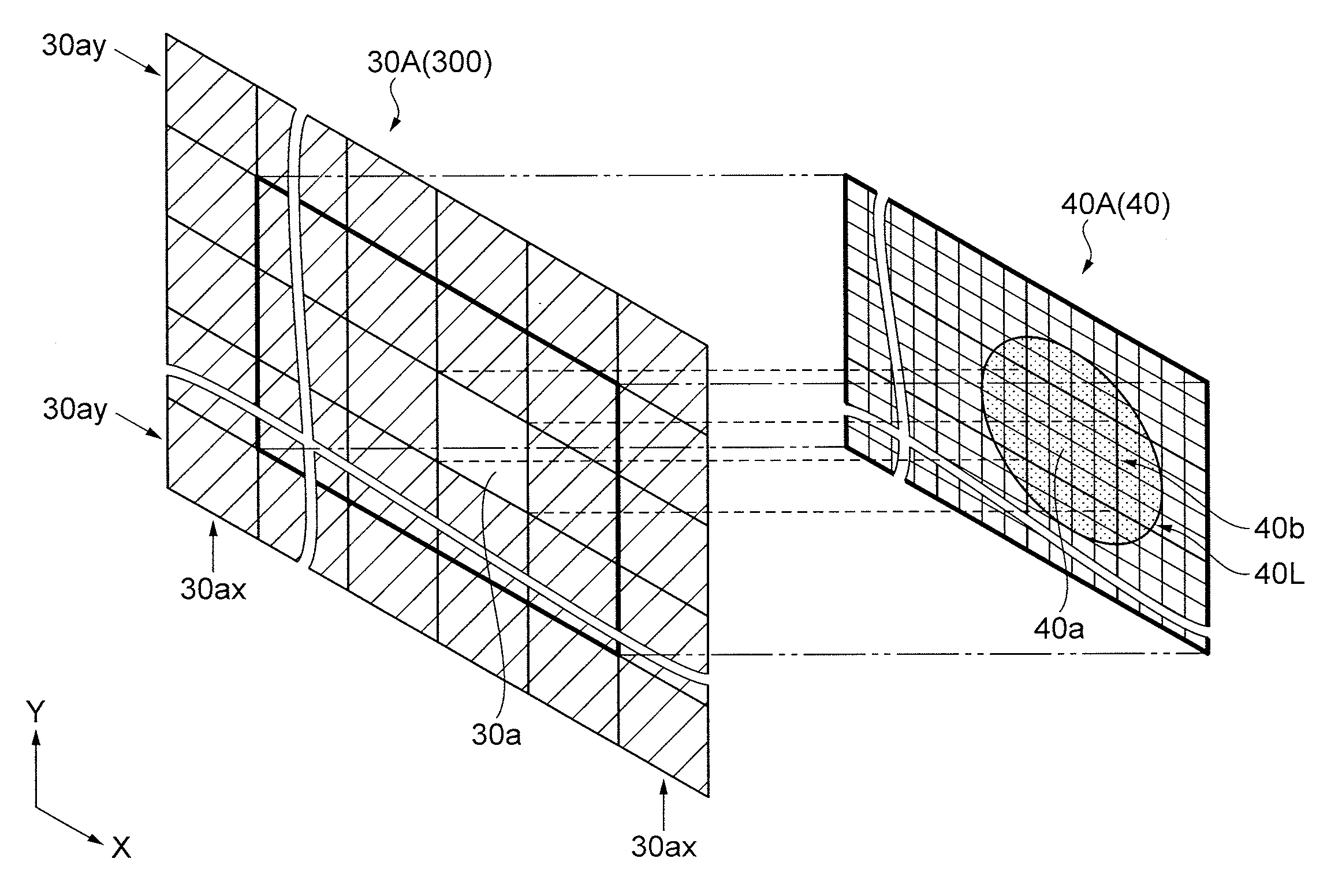
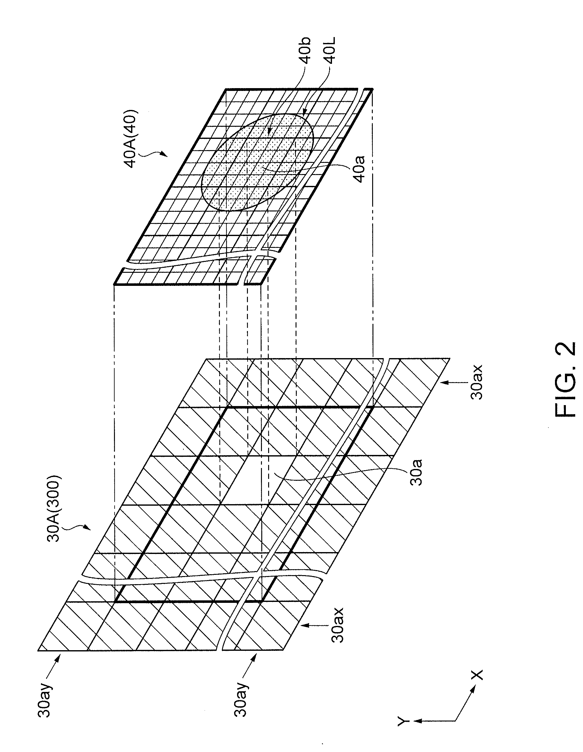
[0018]In the display device according to the application example described above, it is preferable that a light exit side of the plurality of dimming parts and a light incident side of the image forming area are disposed so as to be opposed to each other, and the effective dimming area is larger than the image forming area in a first direction and a second direction perpendicular to the first direction.

[0019]According to this configuration, it is possible to achieve the configuration in which the position of the peak of the intensity distribution of the light emitted from the dimming part located on the outermost side of the effective dimming area is located on the outer edge of the image forming area or outside the image forming area using a simple configuration of forming the effective dimming area to be larger than the image forming area and disposing the plurality of dimming parts and image forming area so as to be opposed to each other. Thus, it becomes possible to realize the ...


PUM


Abstract

A light modulation device having an image forming area in which a plurality of pixels is arranged, and adapted to modulate incident light, and an illumination device adapted to illuminate the image forming area are provided, and the illumination device has an effective dimming area in which a plurality of dimming parts each capable of individually controlling a light intensity of the light for illuminating the image forming area is arranged, illumination areas illuminated by the light emitted from the dimming parts adjacent to each other out of the plurality of dimming parts partially overlap each other, and the light enters the light modulation device, and the position of the peak of the intensity distribution of the light emitted from the dimming part located on the outermost side of the effective dimming area is located on the outer edge of the image forming area or outside the image forming area.

Description

TECHNICAL FIELD[0001]The present invention relates to a display device.BACKGROUND ART[0002]In the past, there has been known a display device, which modulates the light emitted from the light source using a light modulation device to display an image. Incidentally, in recent years, there has been demanded an improvement in image quality due to increase in contrast of the image to be displayed and expansion of a luminance rage (dynamic range) of the image which can be displayed, in order to achieve the improvement in the image quality, there has been proposed a display device provided with a dimming device, which controls the light intensity of the light from a light source in accordance with image information, disposed on an anterior side in an optical path of the light modulation device (see, e.g., PTL 1).[0003]The display device described in PTL 1 is provided with a light source, a first light modulator (a dimming device), an optical system, and a transmissive projection screen, a...

Claims


Application Information

Patent Timeline
IPC IPC(8): H04N9/31
CPCH04N9/3102H04N9/3155H04N9/3152G03B21/208G03B21/005G03B21/14H04N5/74
Inventor OTANI, MAKOTOYAJIMA, AKITAKA
Owner SEIKO EPSON CORP
Why Eureka
Try Eureka