Gear mechanism for rotating drive shaft

Inactive Publication Date: 2016-10-06
THD
View PDF38 Cites 4 Cited by
  • Summary
  • Abstract
  • Description
  • Claims
  • Application Information

AI Technical Summary

Benefits of technology

The present invention provides an improved gear mechanism for rotating the drive shaft of a surgical device. It has three features that make it different from previous designs. First, a linear motion is converted to rotational motion using a gear rack and rotating gear. Second, it prevents multiple fasteners from being deployed with a single pull of the trigger by limiting the movement of the linear element. Third, there is no problem of the trigger not returning to its initial position after being squeezed. The mechanism includes a one-way mechanism that arrests movement of the rotating gear while allowing the strike element to move back to its starting position for the next squeeze of the trigger. The mechanism also includes a cantilevered striking element and a fixed pawl. The surgical device includes a housing, a trigger, a linear movable element, a rotatable gear, a drive shaft, a left-winged or right-winged rotating gear, and a striking element.

Problems solved by technology

Squeezing the trigger rotates the rotatable gear, which causes rotation of the trigger gear, which in turn causes rotation of an idler gear which meshes with a gear train operatively linked to the drive shaft, thereby causing rotation of the drive shaft.
Another problem which must be solved in such tackers is preventing the trigger from returning to its initial position before the trigger has been fully squeezed.

Method used


Image

  • Gear mechanism for rotating drive shaft
  • Gear mechanism for rotating drive shaft
  • Gear mechanism for rotating drive shaft

Examples


Embodiment Construction

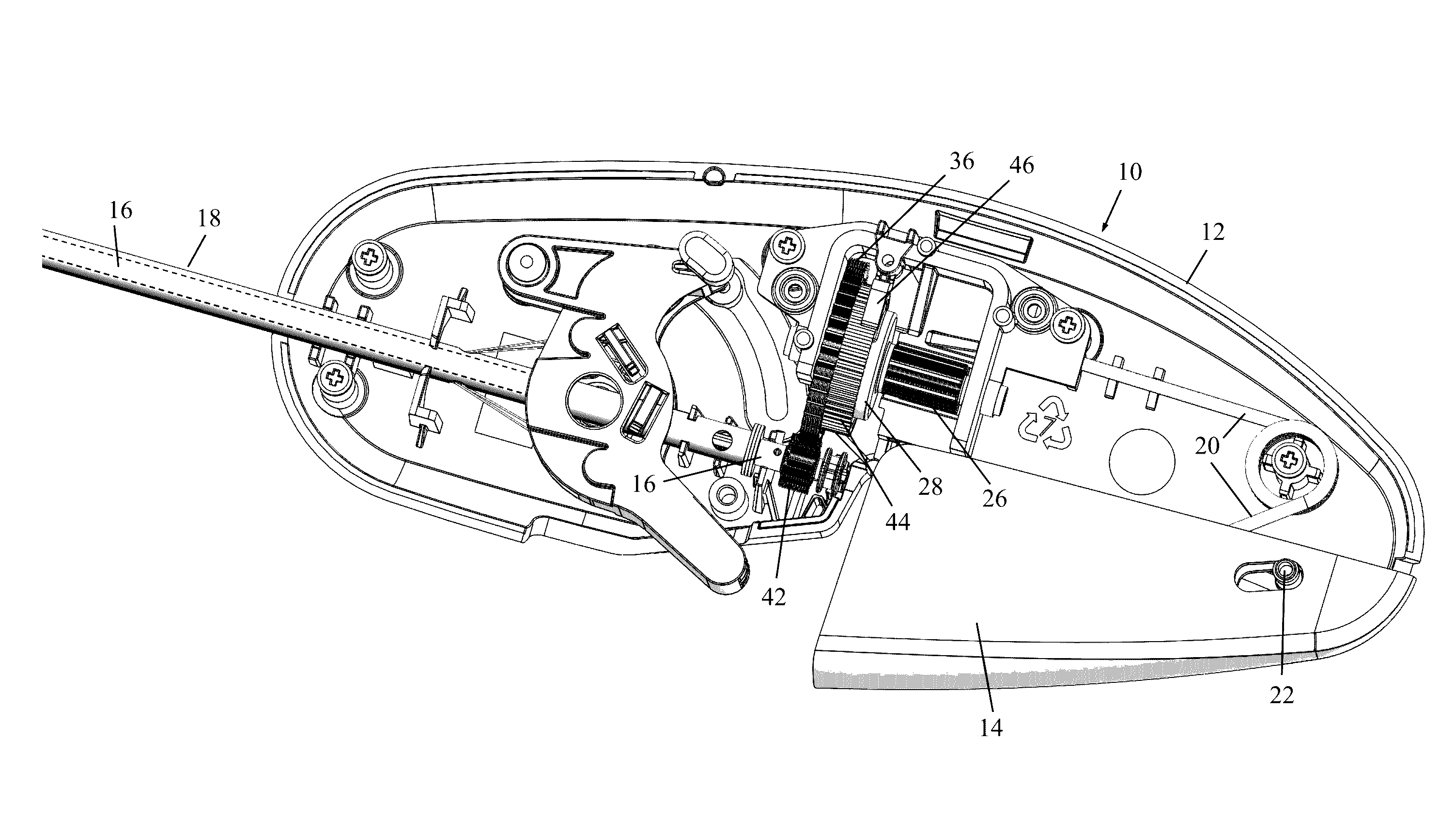
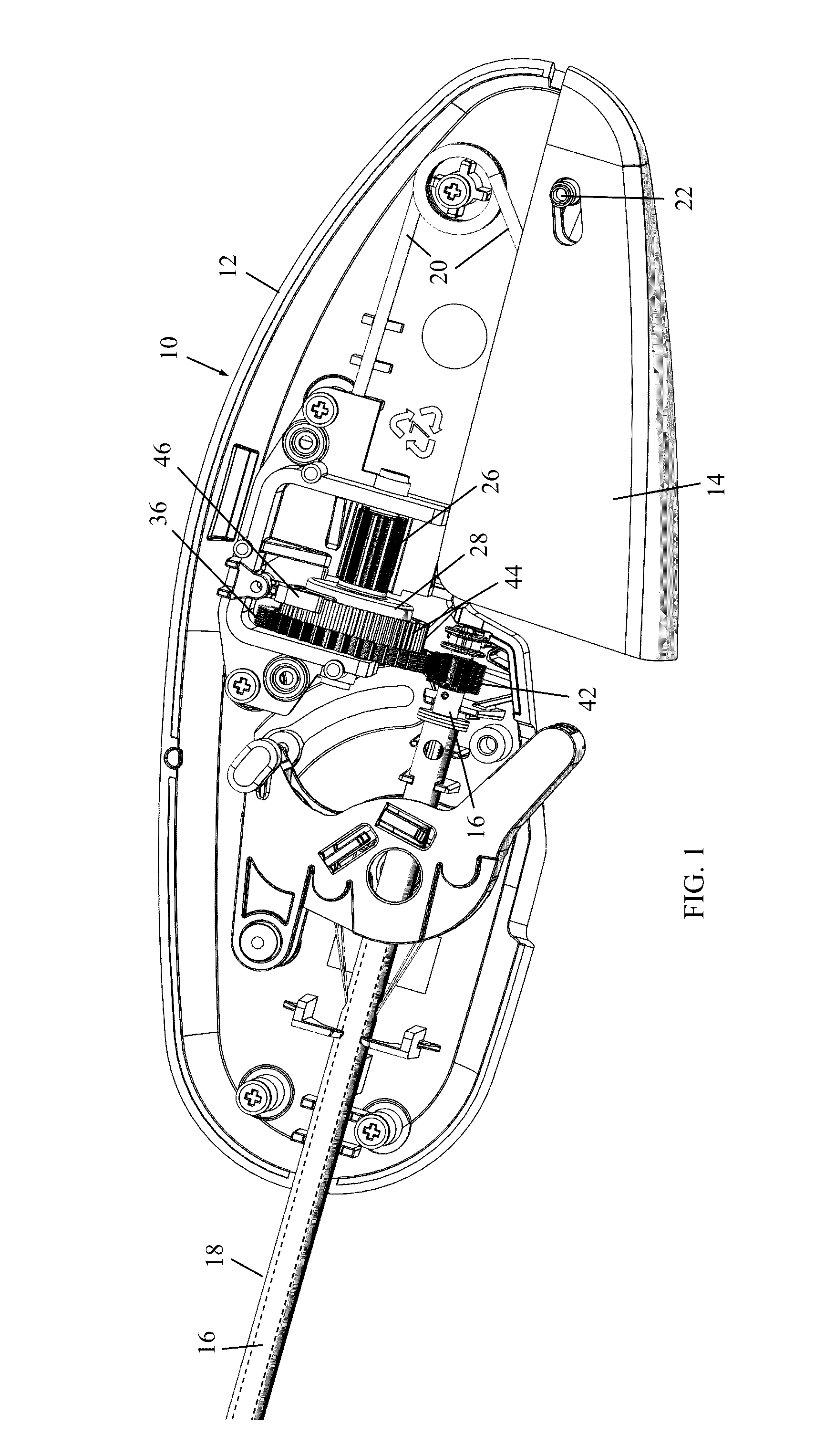
[0021]Reference is now made to FIG. 1, which illustrates surgical device 10 for rotating a drive shaft, constructed and operative in accordance with a non-limiting embodiment of the present invention.

[0022]A housing 12 (also called handle housing or handle) of surgical device 10 houses a deployment trigger 14 (referred to simply as trigger 14) for rotating a drive shaft 16 housed in an outer tube 18. Trigger 14 may be spring-loaded by a spring 20. Trigger 14 pivots about a pivot 22. Squeezing trigger 14 (upwards, clockwise in the sense of the drawing) causes rotation of the drive shaft 16 through a gear train, as is described hereinbelow. An applicator arm (not shown in FIG. 1) is connected to the drive shaft 16. In the case of a tacker, operation of trigger 14 causes the drive shaft 16 to rotate so as to distally advance coil fasteners (e.g., rotary tacks) from the applicator arm for deployment in tissue.

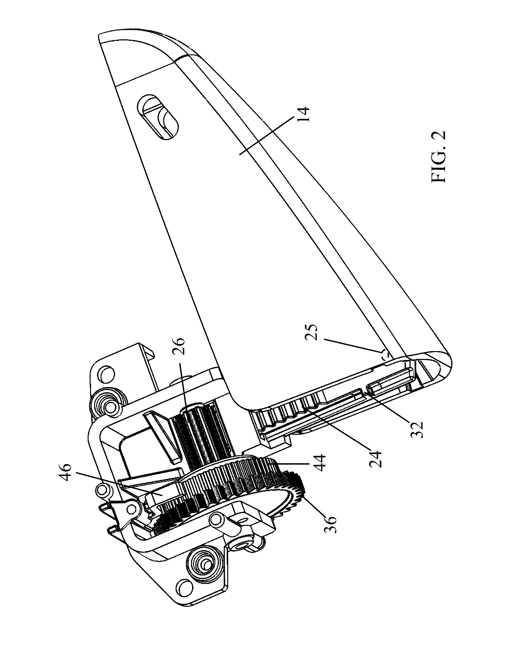
[0023]Reference is now made to FIGS. 2-4, which illustrate the gear train (gea...


PUM


Abstract

A surgical device includes a housing and a trigger connected to the housing. The trigger is arranged to rotate a drive shaft by a gear mechanism. Linear movement of a linear movable element causes rotation of a rotatable gear operatively linked to the drive shaft.

Description

FIELD OF THE INVENTION[0001]The present invention relates generally to surgical devices that have a rotating drive shaft, such as but not limited to, a tacker for applying surgical fasteners, and particularly to a gear mechanism for rotating the drive shaft.BACKGROUND OF THE INVENTION[0002]A number of surgical devices employ a rotating drive shaft, which is used, for example, to deploy surgical devices, such as rotary tacks, in laparoscopic, endoscopic and other procedures, such as for hernia repairs and the like.[0003]Tackers for applying such rotary tacks are well known. A typical tacker drive mechanism of the prior art is described in EP1908409. In this tacker, a rotatable gear is attached to a trigger so that squeezing the trigger rotates the rotatable gear. The rotatable gear meshes with a trigger gear. Squeezing the trigger rotates the rotatable gear, which causes rotation of the trigger gear, which in turn causes rotation of an idler gear which meshes with a gear train operat...

Claims


Application Information

Patent Timeline
IPC IPC(8): A61B17/068F16H31/00A61B17/00F16H19/04
CPCA61B17/068F16H19/04F16H31/001A61B2017/00367F16H2019/046A61B2017/0046A61B17/00234A61B17/00A61B17/10A61B2017/00407A61B2017/2903A61B2017/2923
Inventor LEVIN, SHALOMALTMAN, NIR
Owner THD
Why Eureka
Try Eureka