Cam gear for mechanical locking differential

Inactive Publication Date: 2008-03-06
EATON CORP
View PDF12 Cites 17 Cited by
  • Summary
  • Abstract
  • Description
  • Claims
  • Application Information

AI Technical Summary

Benefits of technology

[0005]The improved differential gear mechanism is characterized by a cam mechanism including a first cam member fixed to rotate with one of said output gears and a second cam member free to rotate relative to said first cam member and said output gear. The first cam member defines a first cam surface and the second cam member defines a second cam surface enga

Problems solved by technology

However, the current process of machining a cam surface into the side gear that engages the cam plate results in an undesirable amount of dimensional variation in the camming surfaces of

Method used


Image

  • Cam gear for mechanical locking differential
  • Cam gear for mechanical locking differential
  • Cam gear for mechanical locking differential

Examples


Embodiment Construction

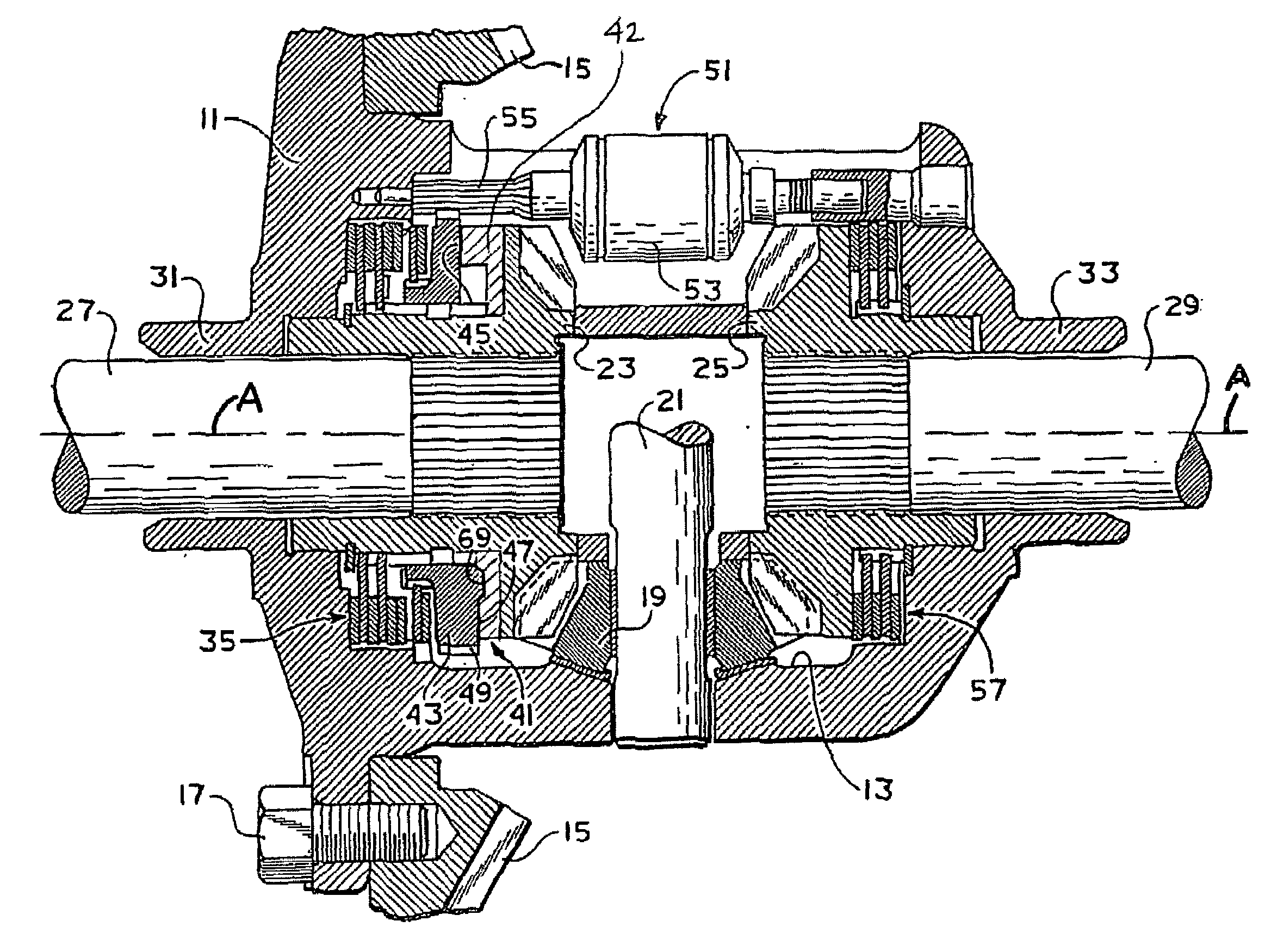
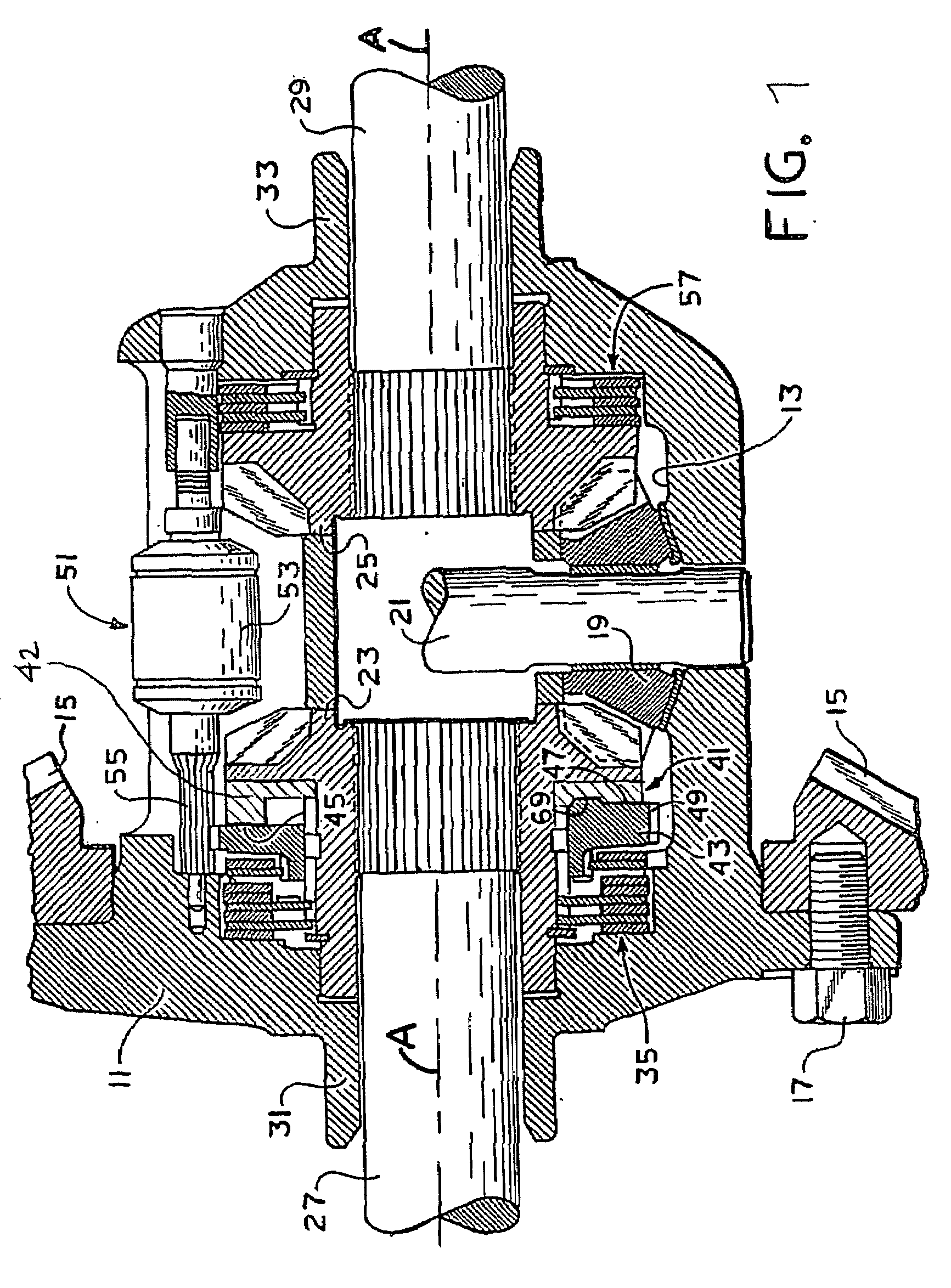
[0012]Referring now to the drawings, which are not intended to limit the invention, FIG. 1 is an axial cross-section of a locking differential gear mechanism of the type that may advantageously utilize the present invention. The differential gear mechanism as shown in FIG. 1 includes a gear case 11 that defines therein a gear chamber, generally designated 13. Torque input to the locking differential is typically by means of an input gear 15 (shown only in fragmentary view in FIG. 1). The input gear 15 (also referred to as a “ring gear”) is intended to be in toothed engagement with an input pinion gear (not shown in FIG. 1), which receives input drive torque from the vehicle driveline. The input gear 15 may be attached to the gear case 11 by means of a plurality of bolts 17.

[0013]Disposed within the gear chamber 13 is a differential gear set including a plurality of pinion gears 19 (only one of which is shown in FIG. 1), rotatably mounted on a pinion shaft 21 (only a portion of which...


PUM


Abstract

An improved differential gear mechanism is characterized by a cam mechanism including a first cam member fixed to rotate with one of said output gears and a second cam member free to rotate relative to said first cam member and said output gear. The first cam member defines a first cam surface and the second cam member defines a second cam surface engagable with the first cam surface to impart movement of the second cam member along axis. The first cam member comprises a powdered metal component, which provides consistency in the cam surface profile and eliminates the substantial capital equipment needed to machine the cam surface.

Description

BACKGROUND OF THE DISCLOSURE[0001]The present invention relates to differential gear mechanisms, and more particularly, to such mechanisms that include a cam mechanism for limiting differentiation. More specifically, the present invention relates to mechanisms of the type also referred to as “mechanical lockers”, i.e., locking differentials in which the locking function occurs in response to the operation of a mechanical device, as opposed to hydraulic actuation or electromagnetic actuation.[0002]A conventional locking differential made by the assignee of the present invention utilizes a flyweight mechanism to initiate the lock-up of the differential clutch, wherein the flyweight mechanism then retards rotation of a cam plate relative to the differential input (i.e., the ring gear and differential case). Locking differentials of the type that utilize a flyweight mechanism to initiate clutch engagement are now well known, and may be made in accordance with the teachings of any one or...

Claims


Application Information

Patent Timeline
IPC IPC(8): F16H48/06F16H48/14F16H48/20
CPCF16H48/08F16H48/22F16H2048/382F16H2048/208F16H48/24F16H48/20
Inventor CURTIS, KENT M.
Owner EATON CORP
Why Eureka
Try Eureka