
Control System and Image Forming System

Active Publication Date: 2016-10-06
BROTHER KOGYO KK
View PDF0 Cites 1 Cited by
  • Summary
  • Abstract
  • Description
  • Claims
  • Application Information

AI Technical Summary

Benefits of technology

The present invention provides a control system that can hold a target in a stable position. This is achieved by determining a holding current value that is a combination of two current values. This results in a more stable holding of the target.

Problems solved by technology

Thus, such conventional image forming systems have the following problem.
Namely, when the driving current has shortage or surplus, a phenomenon such as vibration occurs and the carriage moves from the target stop position.
Similar to the image forming systems described above, when the force, which is not related to power from the motor, acts on a driving target of any other type of image forming apparatus, it is difficult to control the motor so that the driving target is held at the target stop position.

Method used


Image

  • Control System and Image Forming System
  • Control System and Image Forming System
  • Control System and Image Forming System

Examples


first embodiment

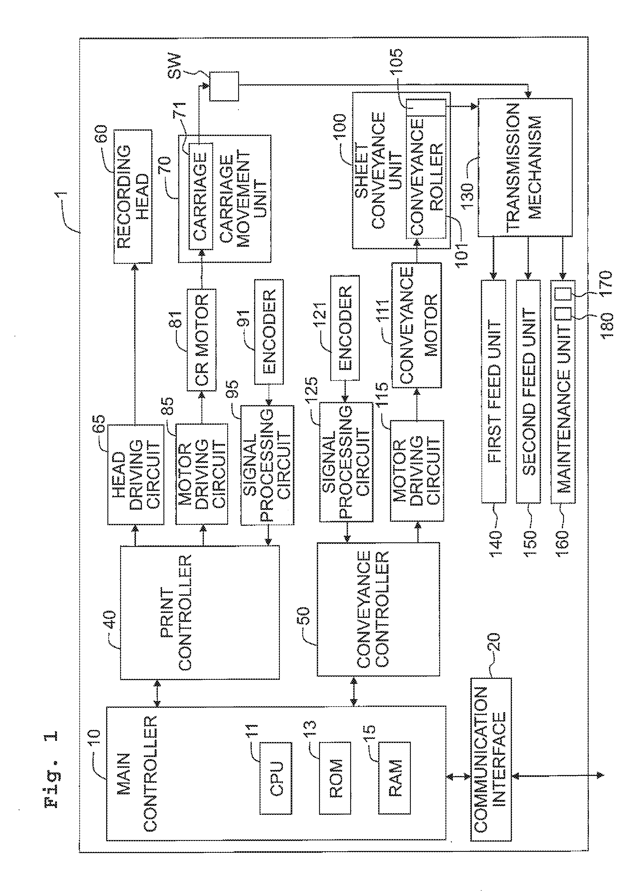
[0037]An image forming system 1 of the first embodiment depicted in FIG. 1 is configured as an ink-jet printer. The image forming system 1 includes a main controller 10, a communication interface 20, a print controller 40, and a conveyance controller 50.

[0038]The main controller 10 includes a CPU 11, a ROM 13, and a RAM 15. Various programs are stored in the ROM 13. The CPU 11 performs processes in accordance with these programs. The RAM 15 is used as a work area when the CPU 11 performs each of the processes. The CPU 11 executes processes in accordance with the programs stored in the ROM 13 to integrally control respective parts of the system, thereby achieving various functions. The communication interface 20 is configured to perform data communication with an external apparatus.

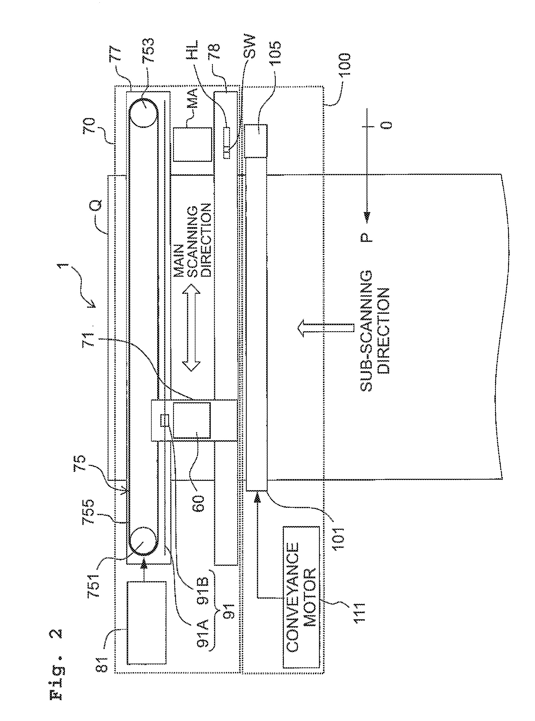
[0039]The print controller 40 is configured to perform an image forming operation on a sheet Q by controlling movement of a carriage 71 (see FIG. 2) carrying a recording head 60 and a discharge operation o...

second embodiment

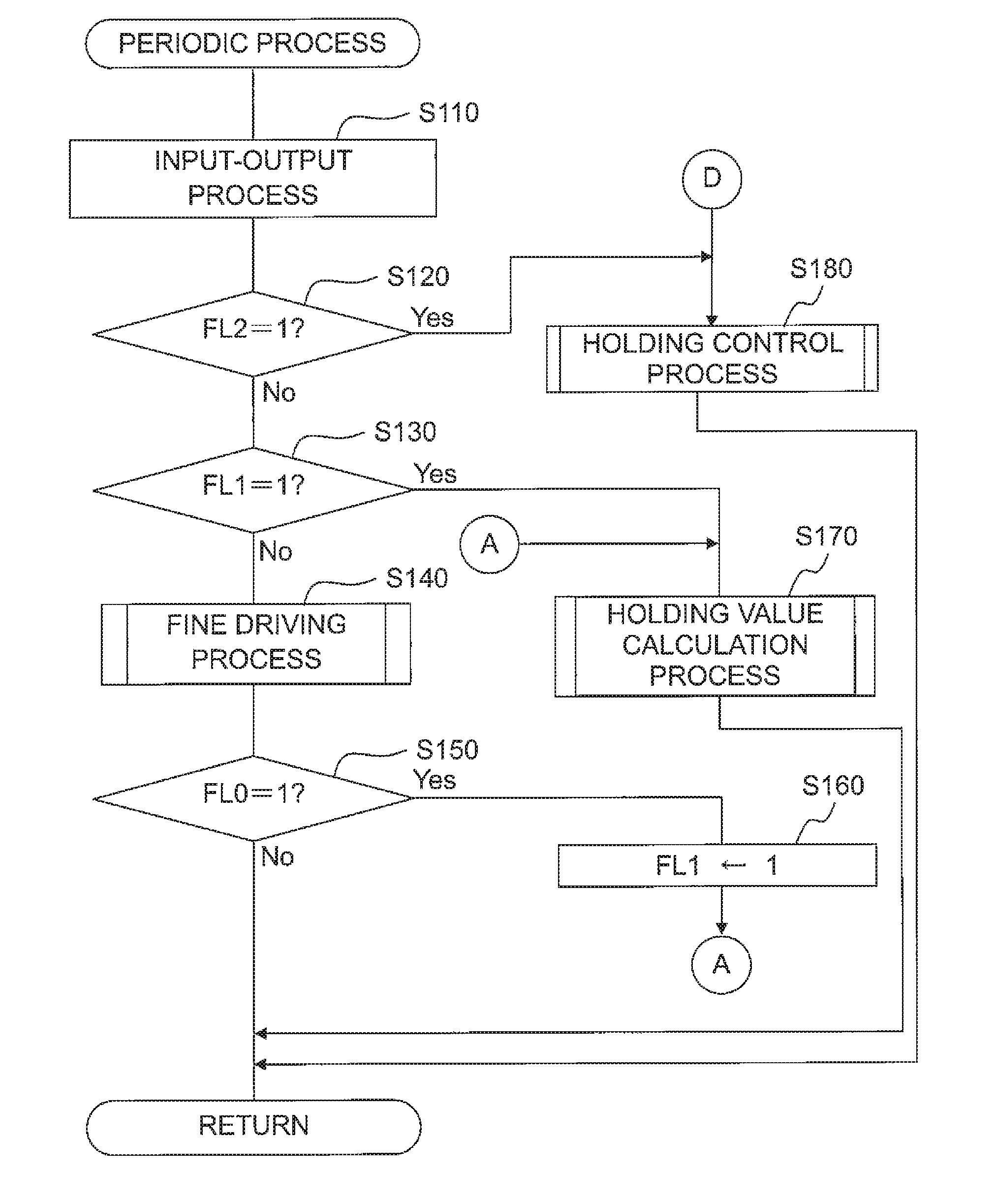
[0122]An explanation will be made about the image forming system 1 of the second embodiment. The image forming system 1 according to the second embodiment has basically the same configuration as that of the image forming system 1 according to the first embodiment, except that the print controller 40 performs a periodic process shown in FIG. 14 instead of the periodic process shown in FIG. 7. In the following, contents of the periodic process executed by the print controller 40 of the second embodiment will be explained selectively. Regarding steps of the periodic process in FIG. 14 which are designated by the same reference numerals as those of the periodic process in FIG. 7, the same processes as those of corresponding steps of the periodic process in FIG. 7 will be performed.

[0123]When the periodic process starts, the print controller 40 judges in S130 whether or not the value of the flag FL1 is set to 1. When the print controller 40 judges that the value of the flag FL1 is not se...

third embodiment

[0129]An explanation will be made about the image forming system 1 of the third embodiment. The image forming system 1 of the third embodiment has basically the same configuration as those of the image forming systems 1 according to the first and second embodiments, except that some of the processes executed by the print controller 40 are different from those of the first and second embodiments. In the following, contents of the processes executed by the print controller 40 of the third embodiment which are different from those of the first and second embodiments will be selectively explained.

[0130]In the image forming system 1 of the third embodiment, when the main controller 10 inputs a movement command causing the carriage 71 to move to the home position, the print controller 40 repeatedly performs a fine reverse-driving process shown in FIG. 15 with a predetermined control period. Repeatedly performing the fine reverse-driving process by the print controller 40 moves the carriag...


PUM


Abstract

A control system includes: a motor; a driving unit including a driving target and displacing the driving target in a first direction and a second direction opposite to the first direction by transmitting power from the motor to the driving target; a detection unit detecting a position of the driving target; and a controller controlling the motor. The controller is configured to execute: a displacement control process to displace the driving target in the first direction and the second direction; a determination process to determine a holding current value holding the driving target at a target stop position; and a holding control process to hold the driving target, which has been disposed at the target stop position in the displacement control process, at the target stop position based on the holding current value determined by the determination process.

Description

CROSS REFERENCE TO RELATED APPLICATION[0001]The present application claims priority from Japanese Patent Application No. 2015-074175 filed on Mar. 31, 2015, the disclosure of which is incorporated herein by reference in its entirety.BACKGROUND[0002]1. Field of the Invention[0003]The present invention relates to a control system and an image forming system.[0004]2. Description of the Related Art[0005]There are conventionally known ink-jet image forming systems. For example, typical ink-jet image forming systems form an image on a sheet, which moves below an ink-jet head discharging ink droplets in a sub-scanning direction, during a process in which a carriage carrying the ink-jet head moves in a main scanning direction.[0006]This type of image forming system includes, for example, a capping unit at an end or terminal (home position) of a carriage movement path. The capping unit is configured to cover a nozzle surface of the ink-jet head with a cap. The capping unit is configured, for...

Claims


Application Information

Patent Timeline
IPC IPC(8): B41J25/00
CPCB41J25/001B41J29/38B41J19/202B41J2/16508B41J2/16511B41J19/207
Inventor HATAKEYAMA, YUICHI
Owner BROTHER KOGYO KK
Learn More