Vibration Unit for Acoustic Module

a technology of vibration unit and acoustic module, which is applied in the direction of transducer details, plane diaphragms, electrical transducers, etc., can solve the problems of unbalanced movement of voice coils, unavoidable movement of vibration diaphragms in lateral directions, and inability to reproduce good sound quality, etc., to achieve improved durability, enhance sound quality, and enhance the effect of secure structur

Active Publication Date: 2016-10-06
HUANG HSIN MIN
View PDF1 Cites 0 Cited by
  • Summary
  • Abstract
  • Description
  • Claims
  • Application Information

AI Technical Summary

Benefits of technology

[0011]Another advantage of the invention is to provide a vibration unit for an acoustic module, wherein the suspension provides a 3-dimensional connection between a vibration member and an encircling frame. The 3-dimensional connection of the suspension will enhance the secure structure to the vibration member and the encircling frame. The 3-dimensional connection of the suspension will also self-generate a repelling force to against a lateral movement of the vibration member so as to ensure the vibration member to be reciprocatingly moved in a linear direction. In other words, any unwanted lateral or radial movement of the vibration member will be restricted by the wave-shaped suspension to ensure the vibration member to be reciprocatingly moved in one linear direction.
[0012]Another advantage of the invention is to provide a vibration unit for an acoustic module, wherein the wavy body of the suspension will generate a pulling force in different directions in response to the displacement of the vibration member so as to stabilize the reciprocating movement of the vibration member in a linear direction.
[0013]Another advantage of the invention is to a vibration unit for an acoustic module, wherein the suspension provides higher sound quality, improve durability, and enhance safety for the acoustic module.
[0014]Another advantage of the invention is to a vibration unit for an acoustic module, wherein the suspension requires minimum installation space in the frame, such that the acoustic module is adapted to equip with any compact product.
[0015]Another advantage of the invention is to a vibration unit for an acoustic module, wherein the manufacturing steps for making the vibration unit is simple so as to lower the manufacturing cost while being time effective.
[0016]Another advantage of the invention is to a vibration unit for an acoustic module, which does not require to alter the original structural design of the acoustic module, so as to minimize the manufacturing cost of the acoustic module incorporating with the vibration unit.

Problems solved by technology

However, the vibration direction of the vibration diaphragm is uncontrollable, such that the vibration diaphragm cannot reproduce good sound quality.
However, the suspension not only allows the vibration diaphragm to move in a vertical direction, for example, but also unavoidably permits the vibration diaphragm to move in a lateral direction.
Accordingly, the unwanted lateral movement of the vibration diaphragm will cause the unbalanced movement of the voice coil.
Once the movement of the voice coil is not aligned with its center axis, the voice coil may scratch the inner side of the speaker frame.
The protective coating of the voice coil will be gradually damaged.
The protruding portion of the suspension will be damaged easily by any external object.
Furthermore, due to the U-shaped cross section of the suspension, the upward displacement of the vibration diaphragm is not the same as the downward displacement thereof In other words, the vibration diaphragm is not reciprocatingly moved in a linear manner.
Therefore, the structure of the speaker with this vibration diaphragm cannot be incorporated with any compact sized electronic device such as laptop, tablet, flat panel television, or mobile phone.

Method used


Image

  • Vibration Unit for Acoustic Module
  • Vibration Unit for Acoustic Module
  • Vibration Unit for Acoustic Module

Examples


Embodiment Construction

[0039]The following description is disclosed to enable any person skilled in the art to make and use the present invention. Preferred embodiments are provided in the following description only as examples and modifications will be apparent to those skilled in the art. The general principles defined in the following description would be applied to other embodiments, alternatives, modifications, equivalents, and applications without departing from the spirit and scope of the present invention.

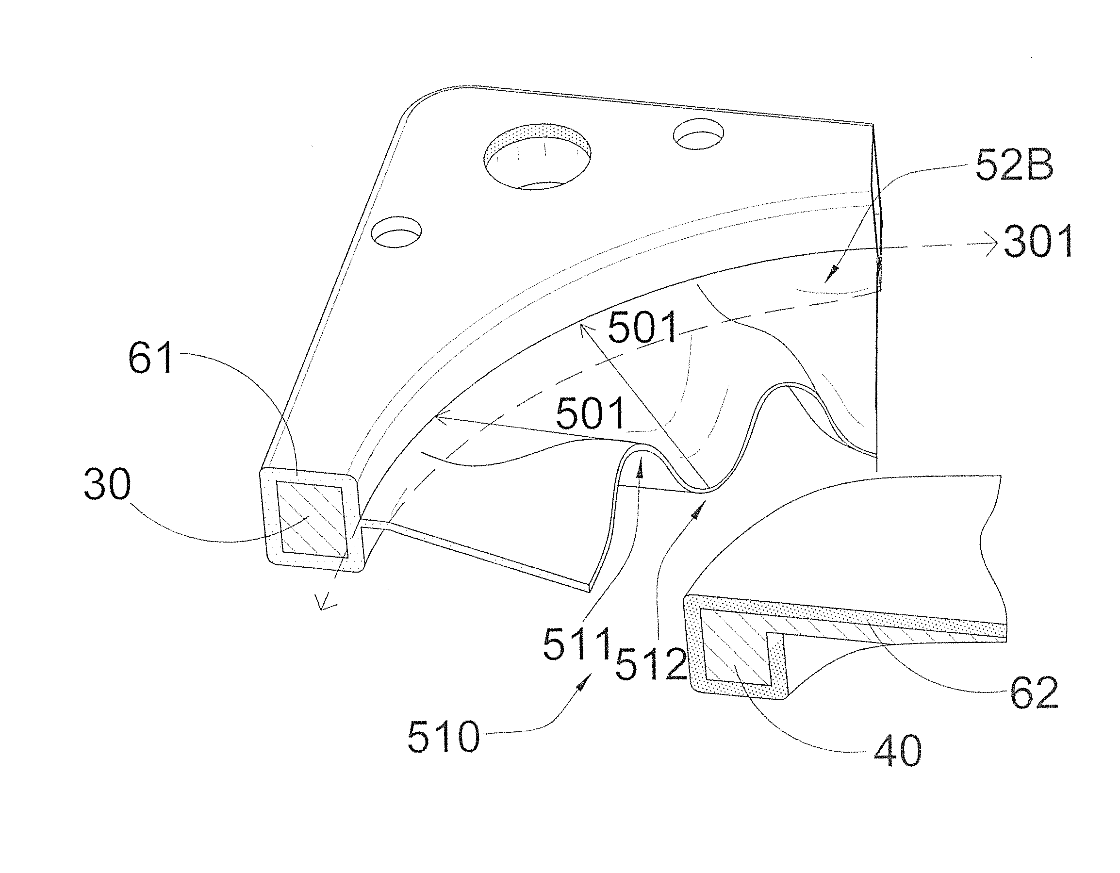
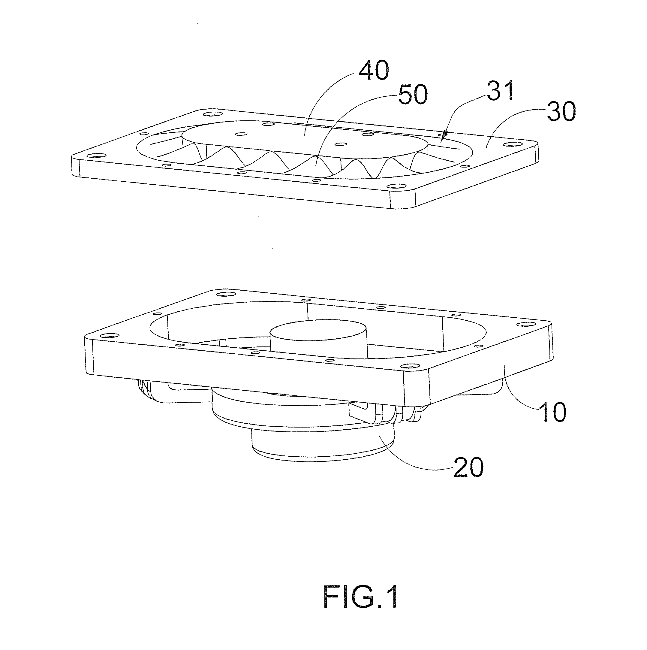
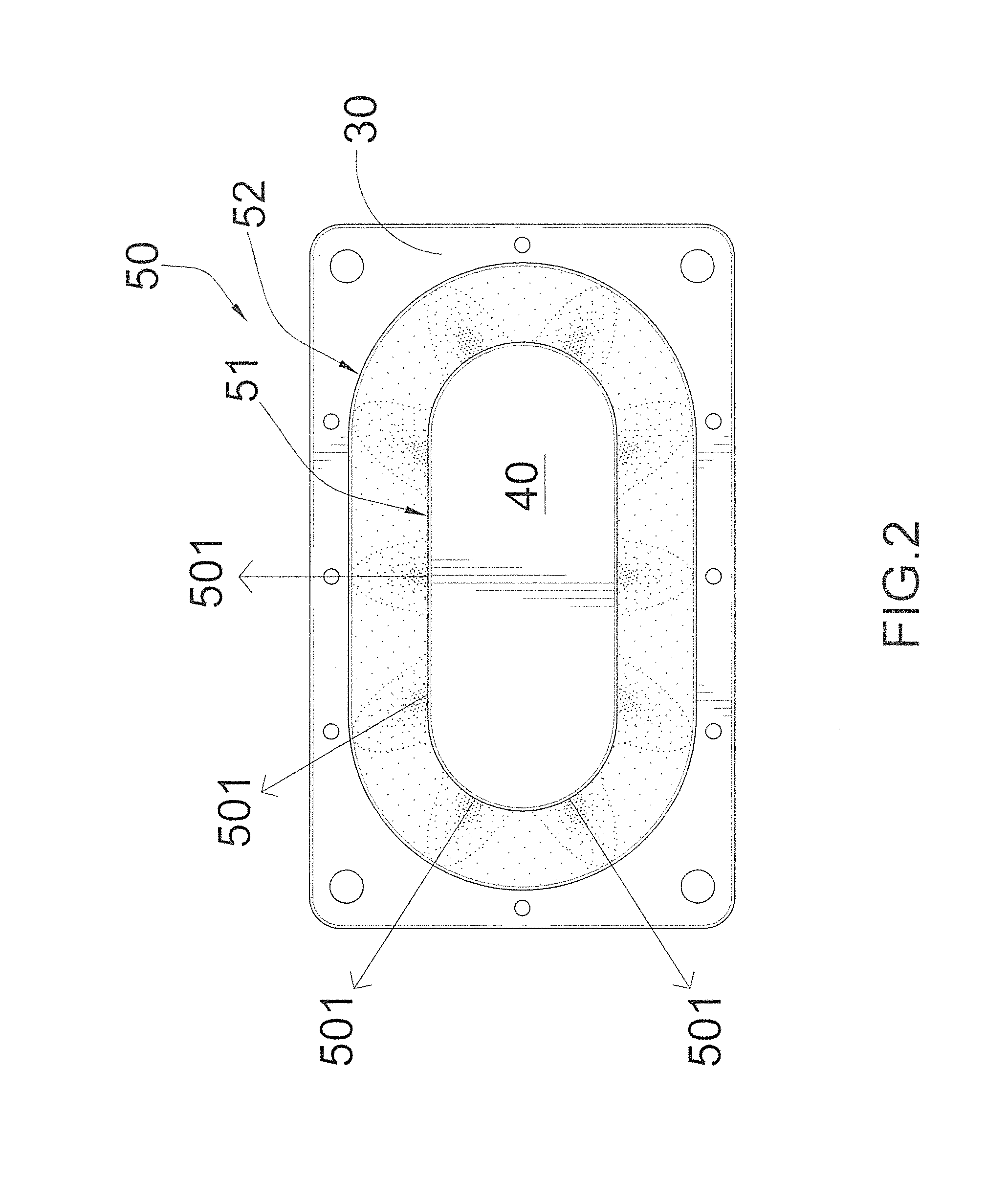
[0040]Referring to FIG. 1 of the drawings, an acoustic module according to a preferred embodiment of the present invention is illustrated, wherein the acoustic module can be formed as a speaker module or equipped with another acoustic module to form a speaker assembly. According to the preferred embodiment, the acoustic module comprises a supporting frame 10, an electromagnetic generator 20, and a vibration unit for providing a vibration effect in response to the electromagnetic generator 20. Acc...


PUM


Abstract

A vibration unit includes an encircling frame defining a vibration cavity therewithin, a vibration member disposed in the vibration cavity, and a suspension including an elastic diaphragm having a periodical wave-shape extended between the vibration member and the encircling frame to support the vibration member within the vibration cavity. The wave-shape diaphragm provides a 3-dimensional connection between the vibration member and the encircling frame to self-generate a repelling force to against a lateral movement of the vibration member so as to ensure the vibration member to be reciprocatingly moved in a linear direction.

Description

CROSS REFERENCE OF RELATED APPLICATION[0001]This is a Continuation application that claims the benefit of priority under 35U.S.C. §119 to a non-provisional application, application Ser. No. 14 / 501,040, filed Sep. 30, 2014.NOTICE OF COPYRIGHT[0002]A portion of the disclosure of this patent document contains material which is subject to copyright protection. The copyright owner has no objection to any reproduction by anyone of the patent disclosure, as it appears in the United States Patent and Trademark Office patent files or records, but otherwise reserves all copyright rights whatsoever.BACKGROUND OF THE PRESENT INVENTION[0003]1. Field of Invention[0004]The present invention relates to a diaphragm for an acoustic device, and more particular to a vibration unit for an acoustic module, wherein the vibration unit comprises a suspension having a wavy configuration to ensure the vibration unit to be reciprocatingly moved in one direction for sound reproduction.[0005]2. Description of Re...

Claims


Application Information

Patent Timeline
Patent Type & Authority Applications(United States)
IPC IPC(8): H04R7/20H04R7/04H04R9/04H04R1/28
CPCH04R7/20H04R1/2834H04R2307/207H04R9/043H04R7/04H04R7/16H04R7/18H04R2400/07
Inventor HUANG, HSIN MIN
Owner HUANG HSIN MIN
Why Eureka
Try Eureka