
A system for controlled defibrillation and ventilation

a technology of defibrillation and ventilation, applied in the field of control of life-saving equipment, can solve the problems of life-threatening, dysfunctional pattern, chaotic electrical activity of the heart,

Active Publication Date: 2016-10-13
INOVYTEC MEDICAL SOLUTIONS
View PDF4 Cites 8 Cited by
  • Summary
  • Abstract
  • Description
  • Claims
  • Application Information

AI Technical Summary

Benefits of technology

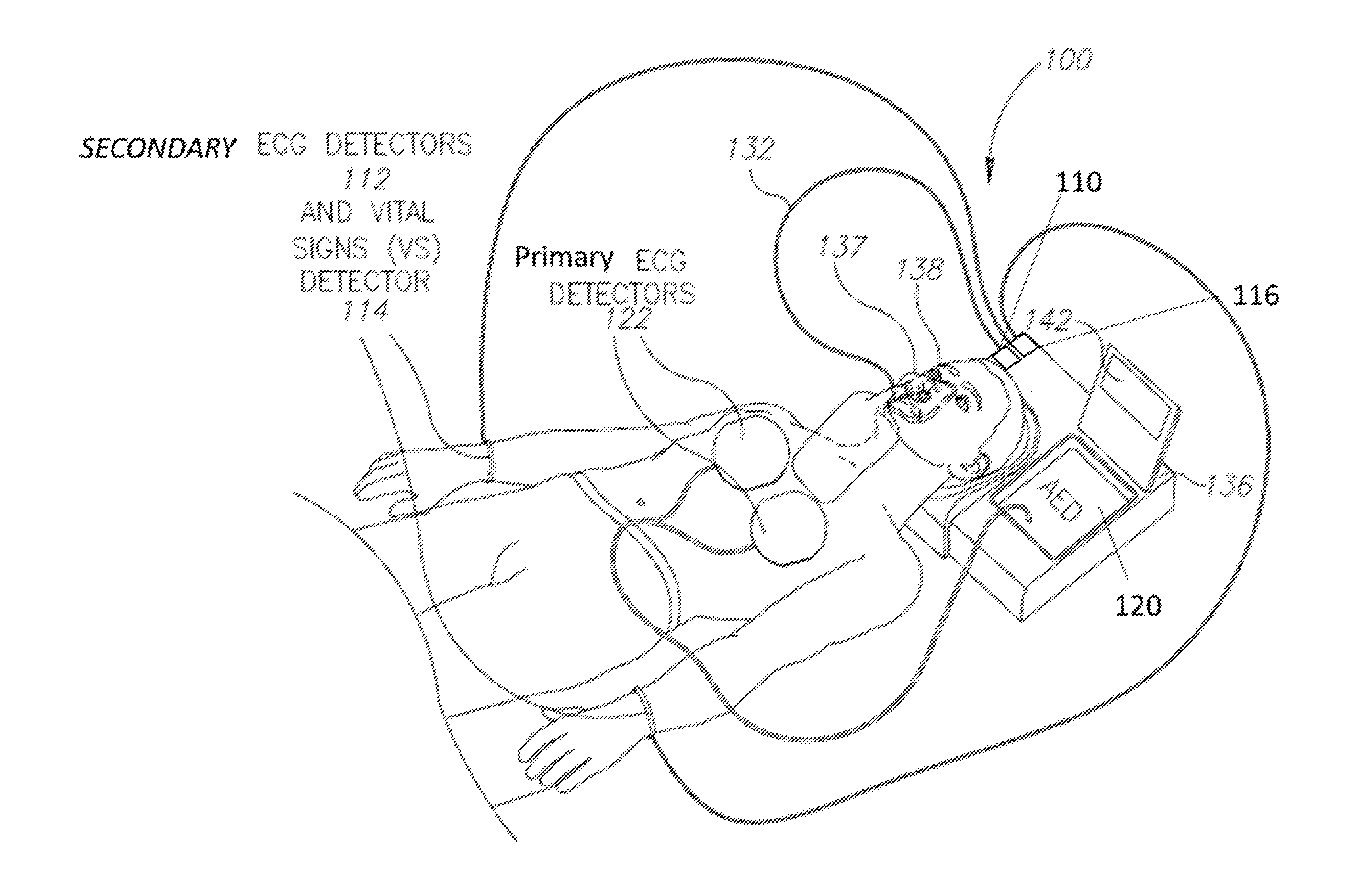
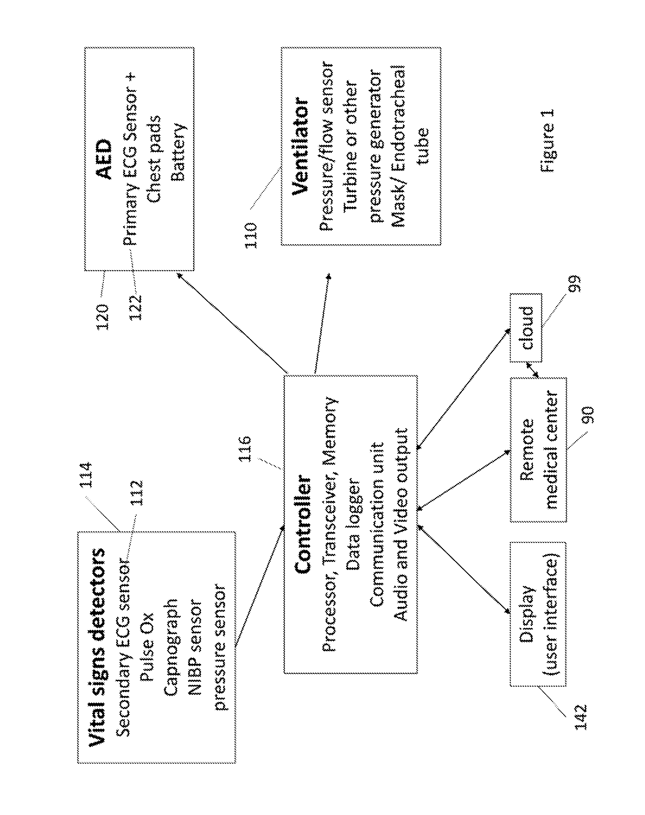
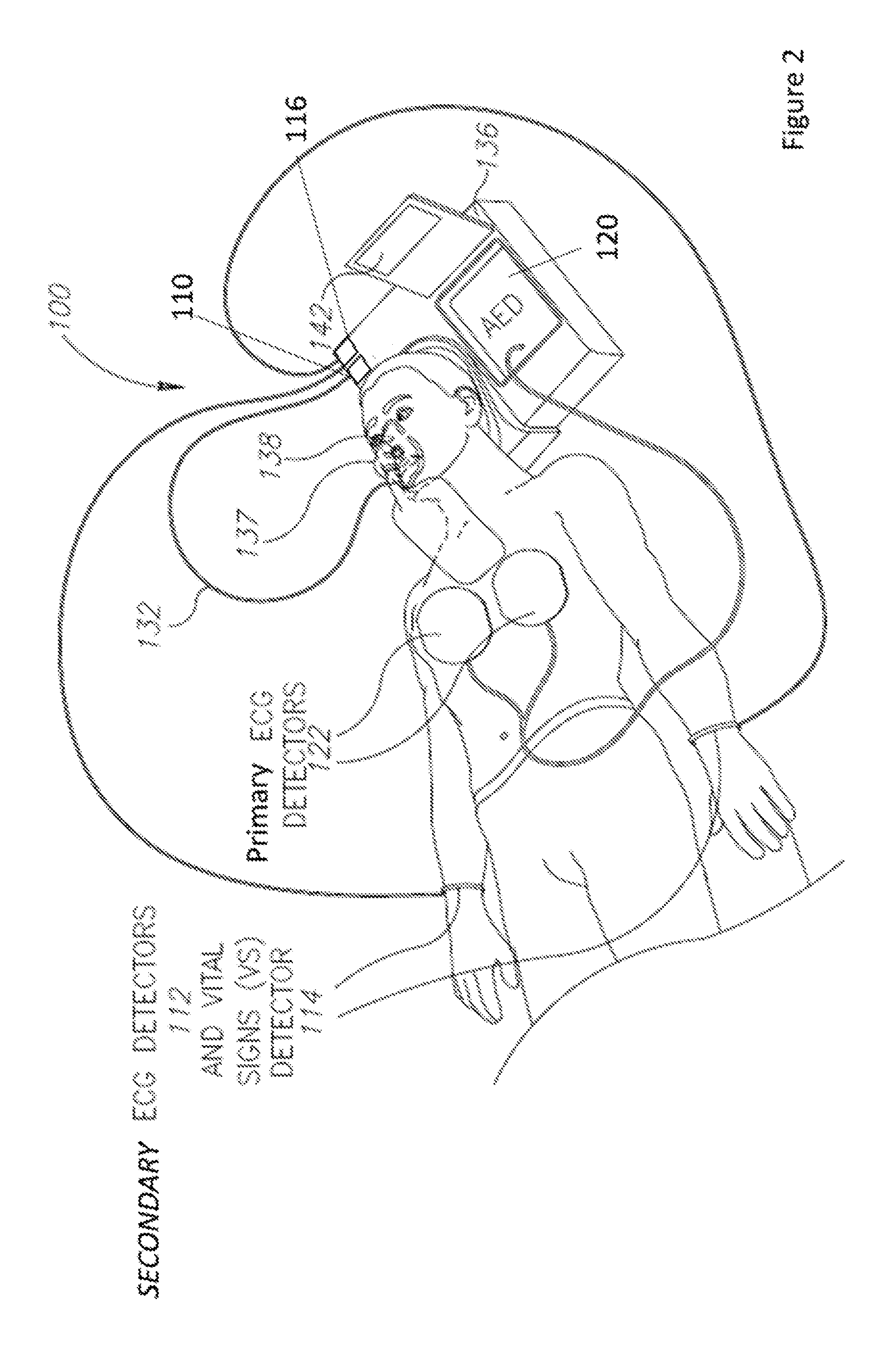
The invention is a system that helps medical professionals provide critical care to patients in emergency situations outside of the hospital. The system includes a ventilator, an Automated External Defibrillator (AED) and sensors that can monitor the patient's vital signs. The controller of the system can activate the AED and place the chest pads on the patient's chest if shockable cardiac arrhythmias are detected. The ventilator can adjust its operation based on readings from the secondary ECG sensors and other vital signs detectors. Overall, the system helps medical professionals provide better care to patients in crisis situations.

Problems solved by technology

Oxygen therapy equipment is generally not available to non-professional users.
In both these types of shockable cardiac arrhythmia, the heart is electrically active, but in a life-threatening, dysfunctional pattern.
In ventricular fibrillation, the electrical activity of the heart is chaotic, preventing the ventricle from effectively pumping blood.
Unfortunately, AEDs solve only a fraction of medical emergencies related to the uncommon occurrence of cardiac arrest.
This may be highly uncomfortable for many people, especially for women or for the elderly.
Few companies provide these two modules in one carrying case.
While the aforementioned system provides guidance to a layperson care giver, it is limited to a ventilation device.

Method used


Image

  • A system for controlled defibrillation and ventilation
  • A system for controlled defibrillation and ventilation
  • A system for controlled defibrillation and ventilation

Examples


Embodiment Construction

[0037]With specific reference now to the drawings in detail, it is stressed that the particulars shown are by way of example and for purposes of illustrative discussion of the preferred embodiments of the present invention only, and are presented in the cause of providing what is believed to be the most useful and readily understood description of the principles and conceptual aspects of the invention. In this regard, no attempt is made to show structural details of the invention in more detail than is necessary for a fundamental understanding of the invention, the description taken with the drawings making apparent to those skilled in the art how the several forms of the invention may be embodied in practice.

[0038]Before explaining at least one embodiment of the invention in detail, it is to be understood that the invention is not limited in its application to the details of construction and the arrangement of the components set forth in the following description or illustrated in ...


PUM


Abstract

The invention is a system for providing decision-assisted critical care to a patient in medical emergency situations in an out of hospital setting. The system comprises: a ventilator comprising a pressure generator and oxygen / air delivery means; an Automated External Defibrillator (AED) comprising a battery and primary electrocardiogram (ECG) sensors configured as chest pads that are configured to be connected to the chest of the patient and to both sense ECG and to deliver an electric shock to the patient's heart; at least one secondary ECG sensor configured to sense ECG but not to deliver electric shock and to be connected to the body of the patient at a location other than the chest; and a controller, configured to activate or instruct a caregiver to activate, the AED and to place the chest pads on the chest of the patient upon detection of shockable cardiac arrhythmias by at least one of the at least one secondary ECG sensors.

Description

BACKGROUND[0001]1. Technical Field[0002]The present invention relates to the field of life saving equipment, and more particularly, to controlling lifesaving equipment designed for the layperson care giver.[0003]2. Discussion of Related Art[0004]Medical emergency situations may occur in various circumstances and affect different body functions such as: trauma injuries, central nerve system injuries (e.g. stroke with apnea), cardiac conditions (e.g. coronary artery disease or cardiac arrhythmias) respiratory conditions (e.g. pulmonary embolism and chronic obstructive lung disorder, or pulmonary spastic disease), there are also systemic conditions such as anaphylactic shock, that affect multiple body functions.[0005]Immediate medical assistance is critical to the effectiveness of life saving treatment in emergency cases. More often than not, professional medical personnel are not present at the scene of occurrence of an emergency situation, leaving the conduct of first emergency care ...

Claims


Application Information

Patent Timeline
Patent Type & Authority Applications(United States)
IPC IPC(8): A61B5/00A61N1/39A61B5/0205A61M16/06A61M16/04A61B5/145A61M16/00A61B5/0402A61B5/332
CPCA61B5/4836A61M16/0057A61N1/3975A61B5/0402A61N1/3993A61M2230/04A61M16/04A61B5/14542A61B5/0205A61B5/082A61M2230/005A61M16/06A61B5/08A61H31/005A61H2230/04A61H2230/40A61M2202/0208A61M2205/05A61M16/125A61H2230/207A61H2230/50A61M16/0051A61M16/024A61N1/39044A61B5/332A61M2202/0007A61B5/318
Inventor KANTOR, EHUDSHAHAR, MARKBARKAI, NIR
Owner INOVYTEC MEDICAL SOLUTIONS
Learn More