Spray arrangement and method for operating a spray arrangement

Active Publication Date: 2016-10-13
LECHLER SPA
View PDF2 Cites 1 Cited by
  • Summary
  • Abstract
  • Description
  • Claims
  • Application Information

AI Technical Summary

Benefits of technology

[0024]In this way, encrustations or blockages of the at least one further nozz

Problems solved by technology

The disadvantage with spray arrangements having return flow nozzles is that, in the regulated r

Method used


Image

  • Spray arrangement and method for operating a spray arrangement
  • Spray arrangement and method for operating a spray arrangement
  • Spray arrangement and method for operating a spray arrangement

Examples


Embodiment Construction

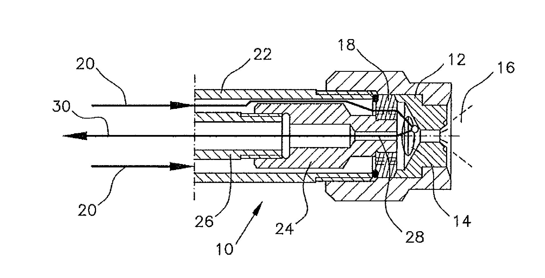
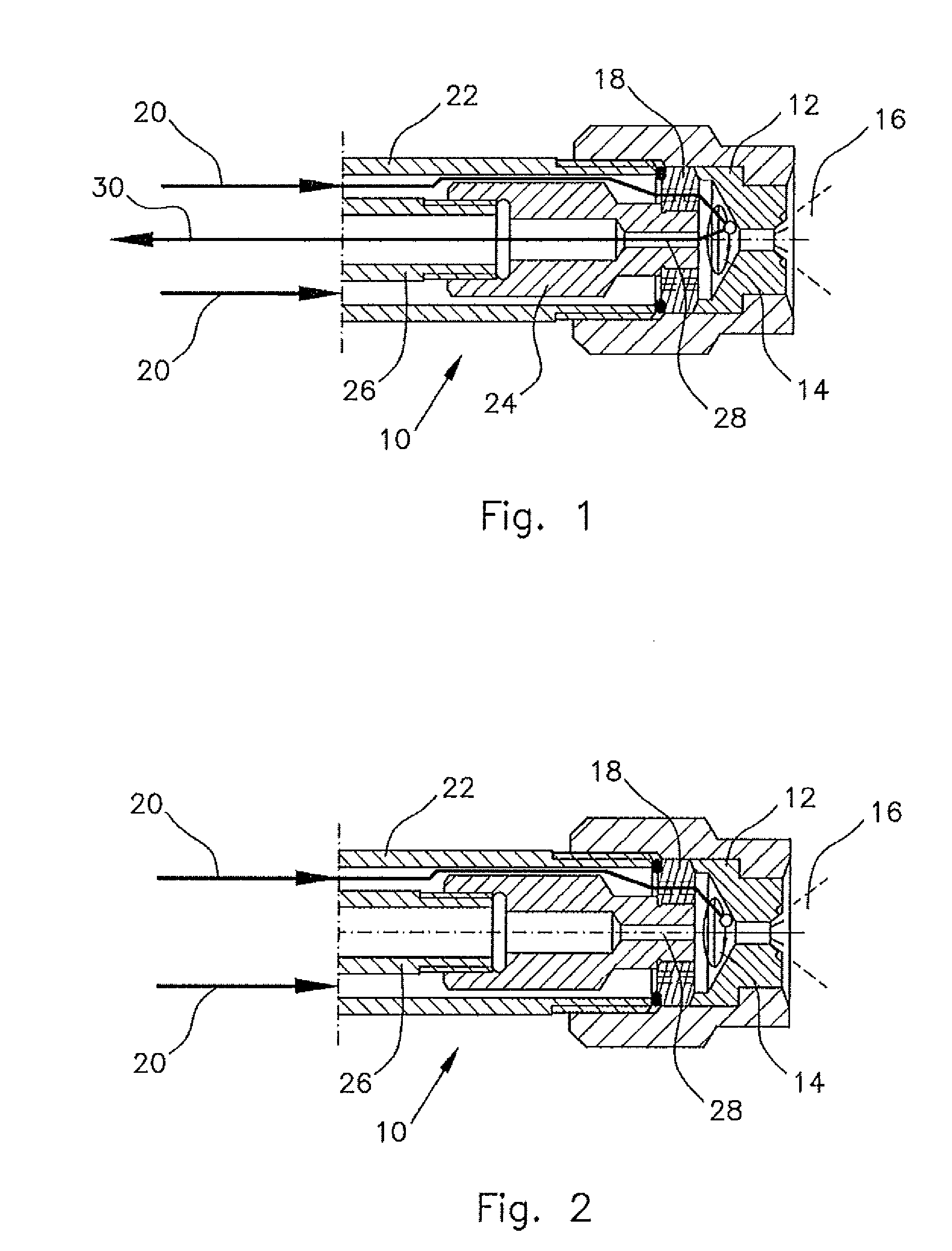
[0030]The illustration in FIG. 1 shows a return flow nozzle 10 in section and serves to explain the mode of operation of the return flow nozzle 10. The return flow nozzle 10 has a housing with a mouthpiece 12, which has a swirl chamber 14 and an outlet opening, from which a spray jet 16 emerges during operation. The liquid to be sprayed moves in a circle within the swirl chamber, this being indicated by a circular arrow in FIG. 1. The liquid within the swirl chamber is fed in via a swirl insert 18, which imparts to the liquid a rotation about a central longitudinal axis of the return flow nozzle 10. Liquid is fed in in the direction of arrows 20 via an inflow line 22. Arranged concentrically within the inflow line 22 is a return connection 24, which is connected to a return line 26, on the one hand, and to the nozzle housing, more specifically to the swirl insert 18, on the other hand. The return connection 24 has a return bore 28, which is connected to the swirl chamber 14, on the ...


PUM


Abstract

Spray arrangement and method for operating a spray arrangement The invention relates to a spray arrangement having at least one return flow nozzle for injecting liquid into a process environment, having a storage tank for the liquid to be injected, at least one return flow nozzle, at least one feed line from the storage tank to the at least one return flow nozzle, at least one pump in the feed line, at least one return line from the return flow nozzle to the storage tank and at least one regulating valve for regulating a liquid quantity injected by the at least one return flow nozzle, wherein at least one further nozzle is provided, which is connected to the feed line by means of a controllable valve for enabling and shutting off a liquid feed.

Description

CROSS-REFERENCE TO RELATED APPLICATIONS[0001]This claims the priority from German Patent Application No. 10 2015 206 548.0, filed on Apr. 13, 2015, the disclosure of which is hereby incorporated by reference in its entirety into this application.FIELD, BACKGROUND AND SUMMARY OF THE INVENTION[0002]The invention relates to a spray arrangement having at least one return flow nozzle for injecting liquid into a process environment, having a storage tank for the liquid to be injected, at least one return flow nozzle, at least one feed line from the storage tank to the at least one return flow nozzle, at least one pump in the feed line, at least one return line from the return flow nozzle to the storage tank and at least one regulating valve for regulating a liquid quantity injected by the at least one return flow nozzle.[0003]Spray arrangements having return flow nozzles have the advantage that the liquid quantity injected can be regulated in a simple manner via the quantity of liquid flo...

Claims


Application Information

Patent Timeline
IPC IPC(8): B01D47/06B05B15/58
CPCB01D47/06F28F25/04F28F25/06B05B1/3093B05B1/3426C10K1/06B01D53/18B01D2259/124B05B9/0423B05B15/55B05B15/58B05B1/30
Inventor ZEEB, THOMAS
Owner LECHLER SPA
Why Eureka
Try Eureka