Efficient dry-type anaerobic fermentation equipment for organic solid waste

A dry anaerobic fermentation, organic solid waste technology, applied in the fields of biochemical equipment and methods, waste fuel, biochemical instruments, etc., can solve the problems of wasting water, poor thermal insulation effect, scattered buildings, etc., to achieve convenient management and maintenance, The effect of avoiding biogas residue crusting and reducing project cost

Inactive Publication Date: 2014-06-25
TIANJIN DESHENGYUAN ENVIRONMENT ENG
View PDF0 Cites 7 Cited by
  • Summary
  • Abstract
  • Description
  • Claims
  • Application Information

AI Technical Summary

Problems solved by technology

[0002] At present, the use of anaerobic equipment to ferment biochemical substances to generate biogas energy has attracted more and more attention. Since the commonly used anaerobic fermentation equipment is mostly wet anaerobic fermentation (water content > 80%), the use of wet anaerobic fermentation equipment to ferment water When using low-efficiency substances, a large amount of water needs to be added, which not only wastes the water source, but also increases the burden for the further treatment of subsequent water
At the same time, this kind of wet anaerobic device also has the following disadvantages: 1. Most of the existing biogas projects adopt the split method. A large number of pipelines need to be connected in reverse, which takes a lot of labor and materials. Because the pipeline connection needs to be highly technical, it is easy to leak, cause a lot of heat loss, occupy a large area, and it is not convenient to operate, manage and maintain, and there are many faults. User inconvenience
2. Low gas production
Because the digestion index of the material in the existing biogas fermentation process is only 50%-60%, the main reason is that the raw material→semi-raw material→clinker→clinker control of the material in the anaerobic digester is not good, resulting in about 40% Undigested raw meal is discharged, thus limiting the improvement of biogas fermentation level
3. Because the project covers a large area and the buildings are scattered, the insulation effect is poor, and the gas production rate is low in winter
4. There are problems of biogas residue crusting and secondary pollution

Method used


Image

  • Efficient dry-type anaerobic fermentation equipment for organic solid waste
  • Efficient dry-type anaerobic fermentation equipment for organic solid waste

Examples


Embodiment Construction

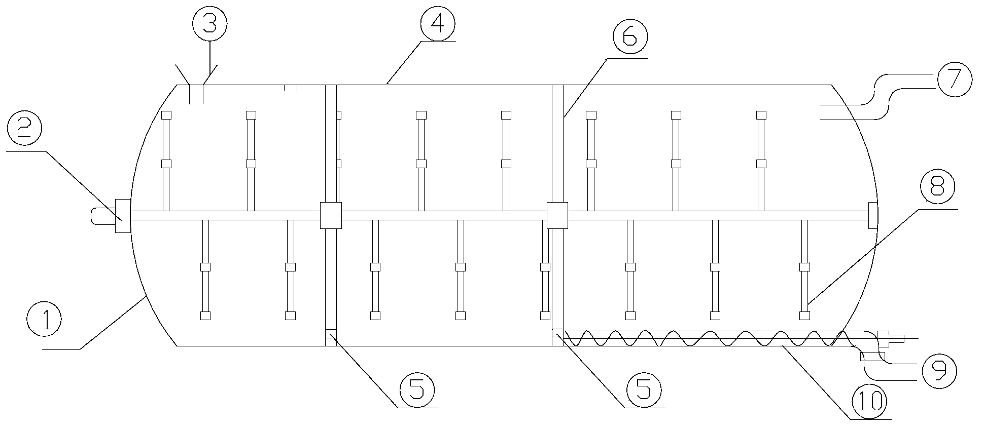
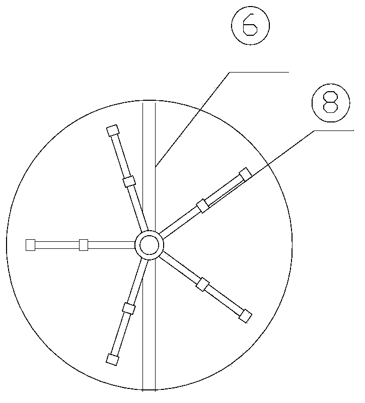
[0016] As shown in the figure: a high-efficiency dry-type anaerobic fermentation equipment for organic solid waste. The horizontal main tank ① has a feed inlet ③ and an air outlet ④ on the top, and the horizontal main tank ① has a slag outlet ⑨ on the bottom. The horizontal main tank ① has a liquid outlet ⑦ on the side; the interior of the main tank is divided into three fermentation chambers by two partitions ⑥, and the agitator ② is inserted horizontally from the center of the main tank, and the agitator ② is fixed on the top. There are stirring blades ⑧, and the bottom of the main tank is equipped with a biogas discharge device ⑩, which communicates with the slag outlet ⑨; the bottom of the partition has a communication hole ⑤. The stirring rod of the above-mentioned agitator runs through the inside of the whole main tank body. The opening of the above-mentioned feed inlet is vertically upward.


PUM


Abstract

An efficient dry-type anaerobic fermentation equipment for organic solid waste is disclosed. A horizontal main tank is provided with a material inlet, a slag outlet, a gas outlet and a liquid outlet; the main tank is inside divided into multiple fermentation chambers by separation plates, a stirrer is horizontally inserted along the center of the main tank, the bottom of the main tank is provided with a biogas discharging device which is communicated with the slag outlet, and the bottom of each separation plate is provided with a communicating pore. The efficient dry-type anaerobic fermentation equipment is high in organic loading, high in gas production efficiency, small in land occupation area and low in energy consumption, and also helps to avoid problems of biogas residue crusting and secondary pollution existed in wet-type anaerobic fermentation.

Description

Technical field: [0001] The invention belongs to a fermentation device, in particular to a high-efficiency dry-type anaerobic fermentation equipment for organic solid waste. Background technique: [0002] At present, the use of anaerobic equipment to ferment biochemical substances to generate biogas energy has attracted more and more attention. Since the commonly used anaerobic fermentation equipment is mostly wet anaerobic fermentation (water content > 80%), the use of wet anaerobic fermentation equipment to ferment water When using low-efficiency substances, a large amount of water needs to be added, which not only wastes the water source, but also increases the burden for the further treatment of subsequent water. At the same time, this kind of wet anaerobic device also has the following disadvantages: 1. Most of the existing biogas projects adopt the split method. A large number of pipelines need to be connected in reverse, which takes a lot of labor and materials. B...

Claims


Application Information

Patent Timeline
Patent Type & Authority Applications(China)
IPC IPC(8): C12M1/107
CPCC12M21/04C12M23/34C12M27/06Y02E50/30
Inventor 王建耕
Owner TIANJIN DESHENGYUAN ENVIRONMENT ENG
Why Eureka
Try Eureka