Method for manufacturing polarizer having locally depolarized area, and polarizer, polarizing plate and image display device manufactured by using same
a manufacturing method and technology of polarizers, which are applied in the direction of polarizing elements, manufacturing tools, instruments, etc., can solve the problems of reducing the visibility of the camera lens, degrading the appearance of the image display device, and difficult to provide varied colors in the area of the display device, so as to achieve excellent heat resistance and maintain the effect of depolarization area
- Summary
- Abstract
- Description
- Claims
- Application Information
AI Technical Summary
Benefits of technology
Problems solved by technology
Method used
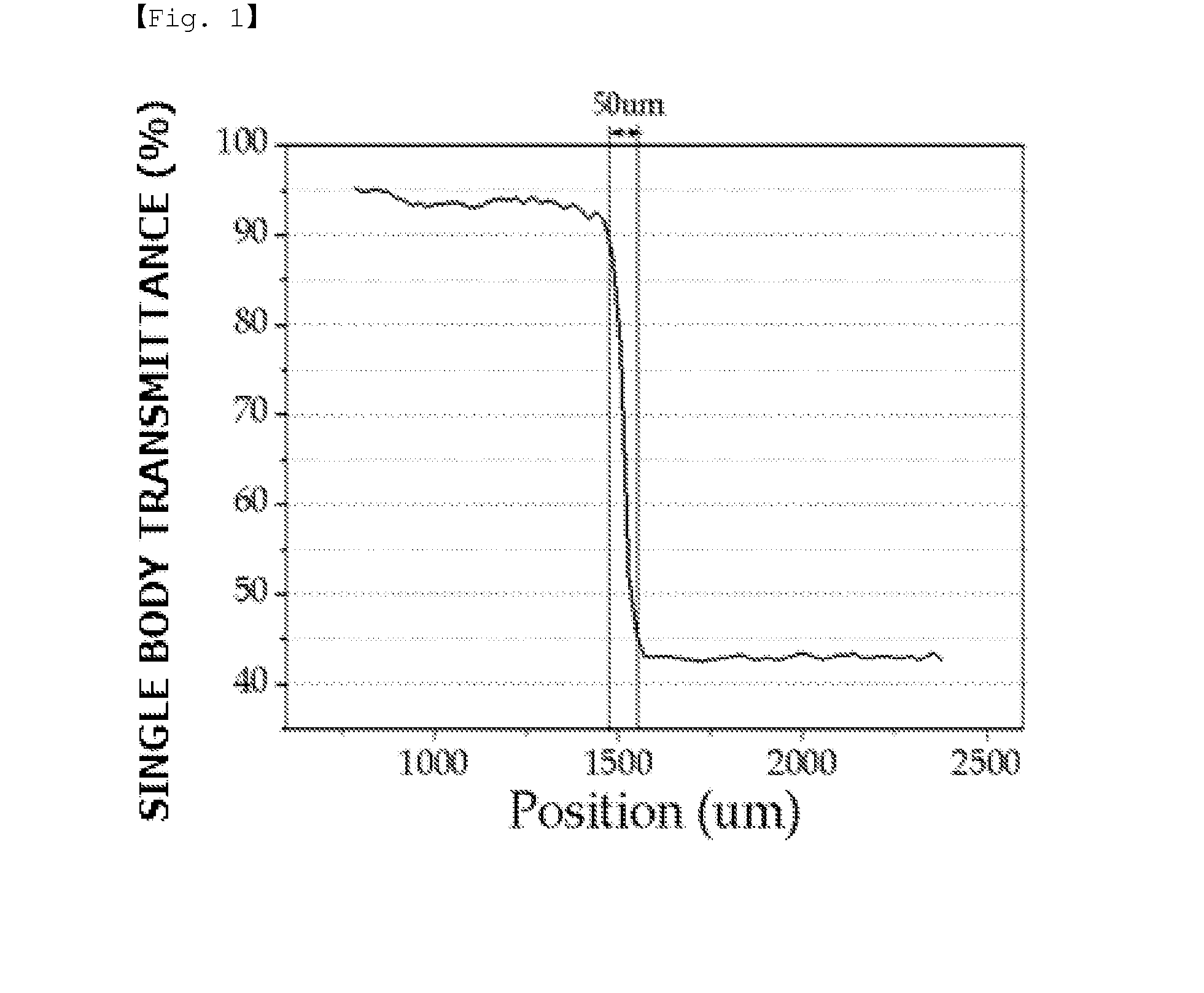
Image

Examples
preparation example 1
Manufacture of Polarizer
[0100]After a polyvinyl alcohol-based film (manufactured by Nippon Synthetic Chemical industry Co., Ltd. M3000 grade 30 μm) went through a swelling process for 15 seconds in purified water at 25° C., a dyeing process was progressed for 60 seconds in an iodine solution of 0.2 wt % concentration and 25° C. After that, a washing process was carried out for 30 seconds in a boric acid solution of 1 wt % and 45° C., and then a process of 6-time elongation was progressed in a boric acid solution of 2.5 wt % and 52° C. After the elongation, a complementary coloring process was carried out in a KI solution of 5 wt %, and the result was dried for 5 minutes in an oven at 60° C. to prepare a polarizer having a thickness of 12 μm.
example 1
[0101]On the polarizer manufactured by the preparation example described above, a bleaching solution (bleaching agent: KOH 15%) was coated on an area of 3 cm2 using a dispenser to form a depolarized area. After 35 seconds passed, the depolarized area was acid treated using acetic acid (manufactured by Daejung Chemicals & Materials Co., Ltd., 10 wt %, pH 2.4) as an acid solution, and a polarizer including a depolarized area was manufactured.
example 2
[0102]A polarizer including a depolarized area was manufactured in the same manner as in Example 1 except that adipic acid (manufactured by Daejung Chemicals & Materials Co., Ltd., 2.4 wt %, pH 2.8) was used as the acid solution for the washing.
PUM
| Property | Measurement | Unit |
|---|---|---|
| Temperature | aaaaa | aaaaa |
| Length | aaaaa | aaaaa |
| Length | aaaaa | aaaaa |
Abstract
Description
Claims
Application Information
 - R&D Engineer
- R&D Manager
- IP Professional
- Industry Leading Data Capabilities
- Powerful AI technology
- Patent DNA Extraction
Browse by: Latest US Patents, China's latest patents, Technical Efficacy Thesaurus, Application Domain, Technology Topic.
© 2024 PatSnap. All rights reserved.Legal|Privacy policy|Modern Slavery Act Transparency Statement|Sitemap