Eureka AIR delivers breakthrough ideas for toughest innovation challenges, trusted by R&D personnel around the world.

Voice coil motor

a voice coil motor and voice coil technology, applied in the direction of mountings, dynamo-electric machines, instruments, etc., can solve the problems of limiting the number of pixels, and the conventional thick voice coil motor cannot meet the demand of thin and compact electronic products such as cameras, mobile phones, etc., and achieve the effect of thinning the voice coil motor

Active Publication Date: 2016-10-20
SAE MAGNETICS (HK) LTD
View PDF22 Cites 4 Cited by
  • Summary
  • Abstract
  • Description
  • Claims
  • Application Information

AI Technical Summary

Benefits of technology

The present invention provides a voice coil motor with a spacer assembly, which reduces the thickness of the motor and improves its performance and practicability. This is achieved by eliminating the use of a base with cover edge and connecting the second spring plate to either the magnetic element or the housing through the spacer assembly.

Problems solved by technology

Furthermore, when the voice coil motor is applicable to cameras, the pixels will be restricted.
By this token, the conventional thick voice coil motor can not meet the demand of thin and compact electronic products such as cameras, mobile phones, etc.

Method used


Image

  • Voice coil motor
  • Voice coil motor
  • Voice coil motor

Examples


first embodiment

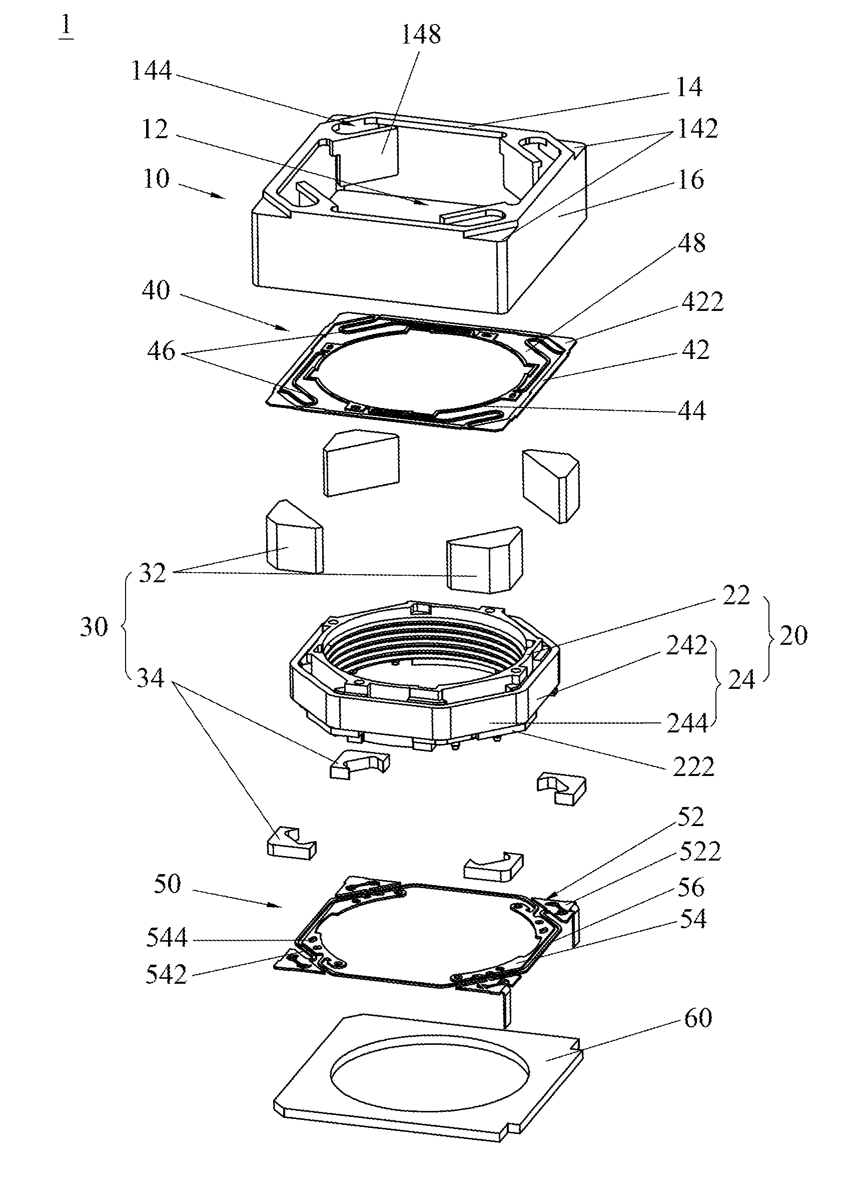
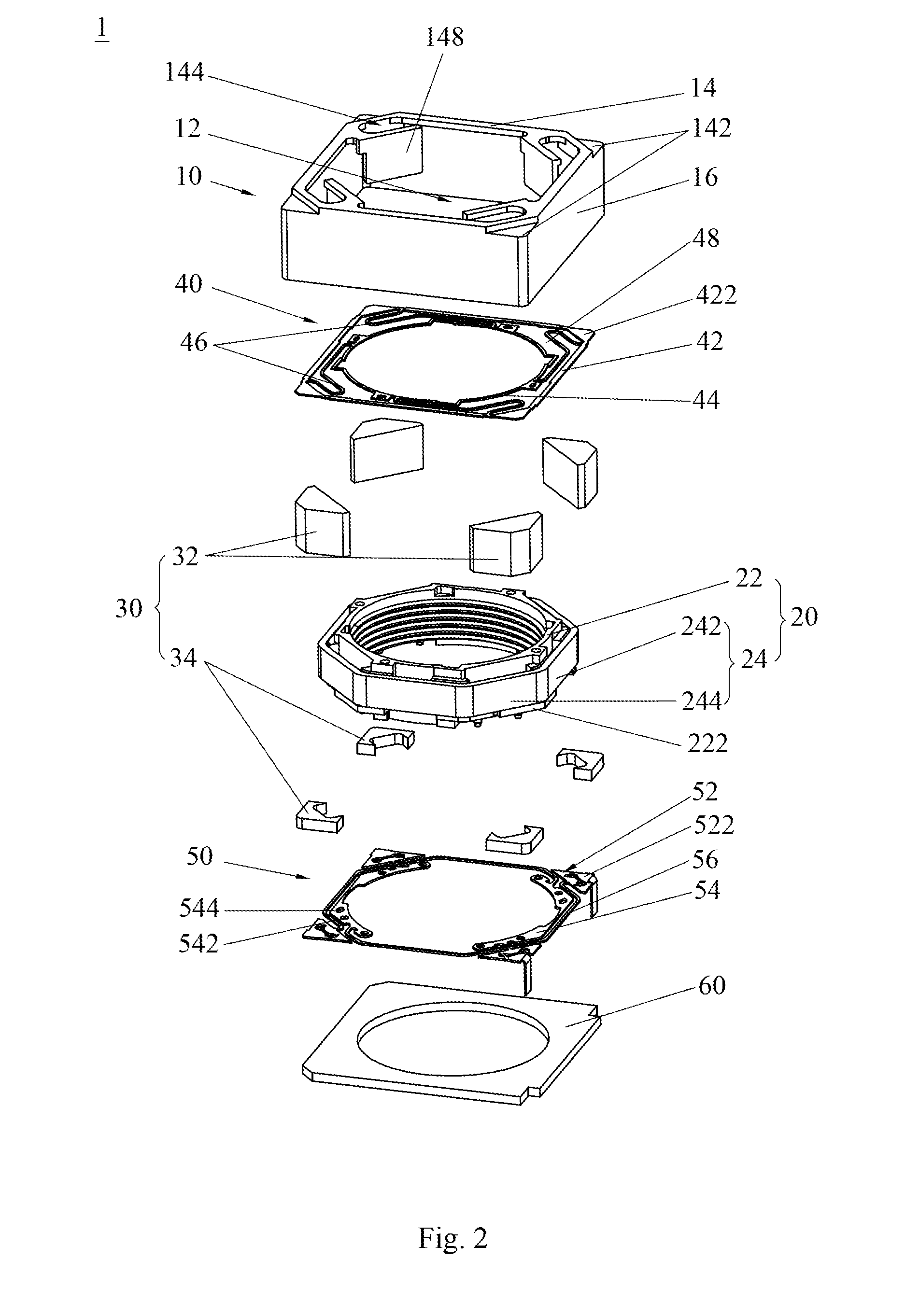
[0042]FIGS. 2 to 3 show a voice coil motor 1 according to a As illustrated, the voice coil motor 1 include a housing 10 having a cavity 12, a movable assembly 20 received in the cavity 12, a fixing assembly 30 configured outside of the movable assembly 20, and a first spring plate 40 and a second spring plate 50 configured at an upper surface and a lower surface of the movable assembly 20 respectively. Specifically, the fixing assembly 30 includes at least two magnetic elements and a spacer member 34. In the embodiment, the magnetic elements include four magnets 32 which are shaped in triangular prism substantially, and the spacer member 34 includes at least two spacers, e.g. four spacers preferably.

[0043]More specifically, the housing has a foursquare top plate 14 and four side plates 16 vertically to the top plate to define the cavity 12, and four first fixing portions 142 are provided at four corners of the top plate 14 respectively.

[0044]As shown in FIG. 2, the movable assembly...

third embodiment

[0052]FIG. 16 shows the present invention. Compared with the second one, the spacer member 34 in the present embodiment includes a frame 342 and at least two connecting arms 344 extended downward from the frame 342 and connected with the second outer frame 52. Preferably, four connecting arms 344 are located at four corners of the frame 342, and the magnet 32 is located between two connecting arms 344. The upper and lower surfaces of the frame 342 are connected with the top plate 14 and the first outer frame respectively, and the first outer frame 42 is connected with the magnets 32. Such a structure of the spacer member 34 may make the voice coil motor 1 more thinner with no base 60.


PUM


Abstract

A voice coil motor includes a housing having a cavity; a movable assembly received in the cavity; a fixing assembly configured outside of the movable assembly; and a first spring plate and a second spring plate configured at an upper surface and a lower surface of the movable assembly respectively. The fixing assembly comprises at least two magnetic elements connected with the first spring plate and a spacer member configured on the second spring plate to connect the second spring plate to the magnetic elements or the housing. The voice coil motor is served as an actuator of electronic products such as digital cameras, mobile phones, and digital cameras, which has thin thickness, good performance and strong applicability.

Description

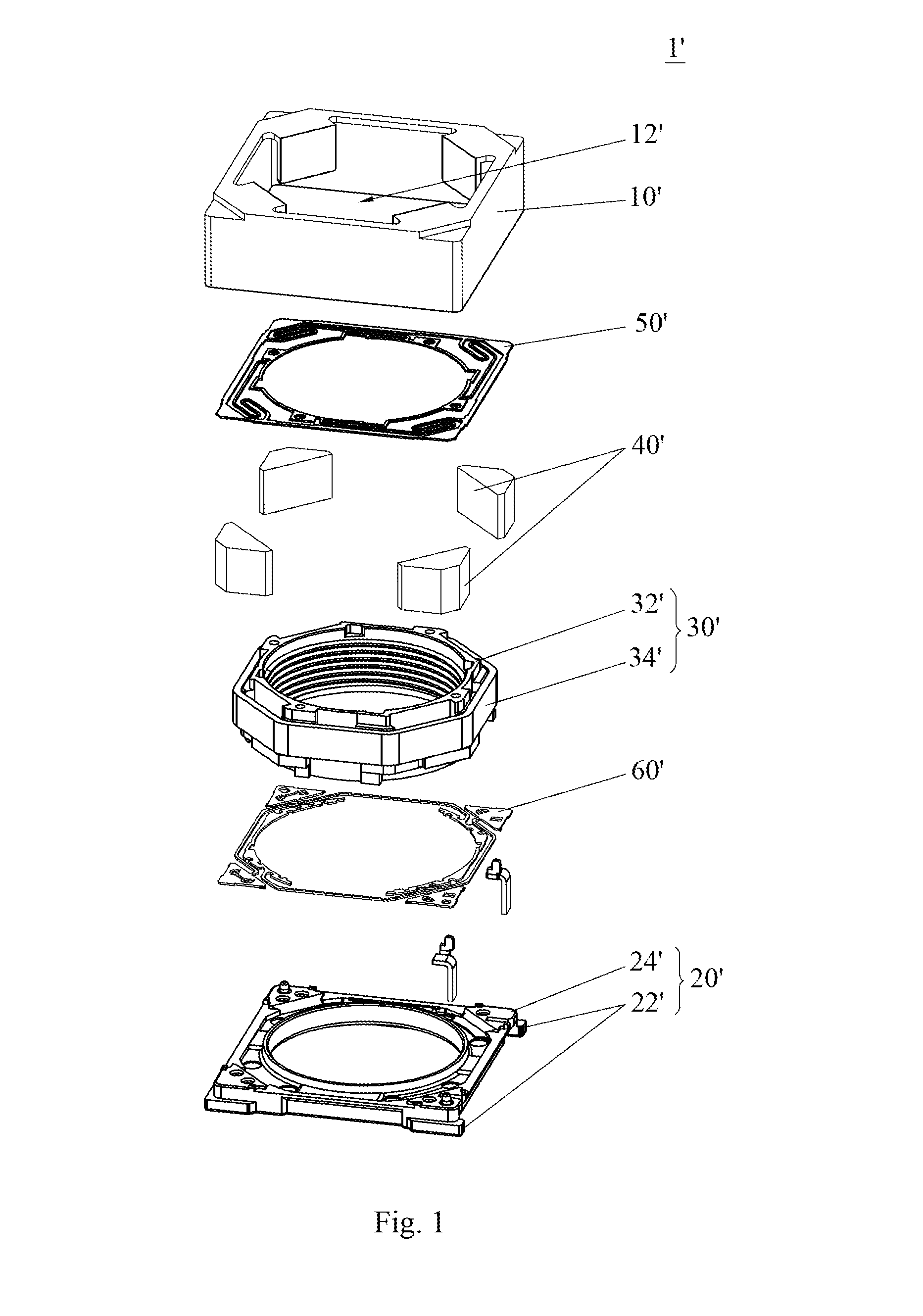
RELATED APPLICATIONS[0001]This application claims the benefit of priority to Chinese Application No. 201520239977.9, filed Apr. 20, 2015, which is hereby incorporated by reference in its entirety.FIELD OF THE INVENTION[0002]The present invention relates to technical field of voice coil motors and, more particularly to voice coil motor having thin and compact structure.BACKGROUND OF THE INVENTION[0003]Voice coil motors are used as actuators of electronic products (such as digital cameras, mobile phones, and digital cameras etc.) as they have small size, low price and save power.[0004]As shown in FIG. 1, a conventional voice coil motor 1′ includes a housing 10′, a base 20′, a movable assembly 30′, four magnets 40′ around the movable assembly 30′, a top spring plate 50′ and a bottom spring plate 60′ located at the upper and lower surfaces of the movable assembly 30′ respectively. A cavity 12′ is defined by the housing 10′ and the base 20′, in which the movable assembly 30′ is installed...

Claims


Application Information

Patent Timeline
Patent Type & Authority Applications(United States)
IPC IPC(8): H02K41/035G02B27/64G02B7/02
CPCH02K41/0356G02B27/646G02B7/023G02B7/08
Inventor CHOU, SIDNEYHO, YIU SINGYIP, KAM FUNGYANG, WEN JUWU, HAI YANGGAO, SHOU SHENGHU, YONG BINGLU, GUO HONG
Owner SAE MAGNETICS (HK) LTD
Why Eureka
Eureka Blog
Learn More