Photovoltaic mounting system

a photovoltaic array and mounting system technology, applied in the direction of photovoltaic supports, heat collector mounting/supports, light and heating apparatus, etc., can solve the problems of increasing the cost of installation, requiring significant time, and requiring additional components and/or reinstallation altogether, so as to reduce the tim

Active Publication Date: 2016-10-20
TESLA INC
View PDF18 Cites 18 Cited by
  • Summary
  • Abstract
  • Description
  • Claims
  • Application Information

AI Technical Summary

Benefits of technology

[0005]Since the coupling assemblies are slidable along the length of the base members, the placement of the base members does not need to be pre-determined. In other words, the slidability of the coupling assemblies during installation allows for some flexibility in at least one direction and may reduce the time spent prior to assembly planning the exact location of the mounting of base members. Furthermore, the flexibility in placement of the coupling assemblies may also help avoid the need of additional components that might otherwise be needed, for example, as a result of conflicts between mounting components.

Problems solved by technology

Assembling photovoltaic arrays is typically a time consuming process.
In many installations, this may require significant time spent planning once at the installation site to determine particular locations for a variety of mounting components.
When exact locations aren't correctly determined, adjustments often require additional components and / or reinstallation altogether as well as roof repairs.

Method used


Image

  • Photovoltaic mounting system
  • Photovoltaic mounting system
  • Photovoltaic mounting system

Examples


Embodiment Construction

[0042]The following description is presented to enable any person skilled in the art to make and use the embodiments, and is provided in the context of a particular application and its requirements. Various modifications to the disclosed embodiments will be readily apparent to those skilled in the art, and the general principles defined herein may be applied to other embodiments and applications without departing from the spirit and scope of the disclosure. Thus, the invention is not limited to the embodiments described and shown.

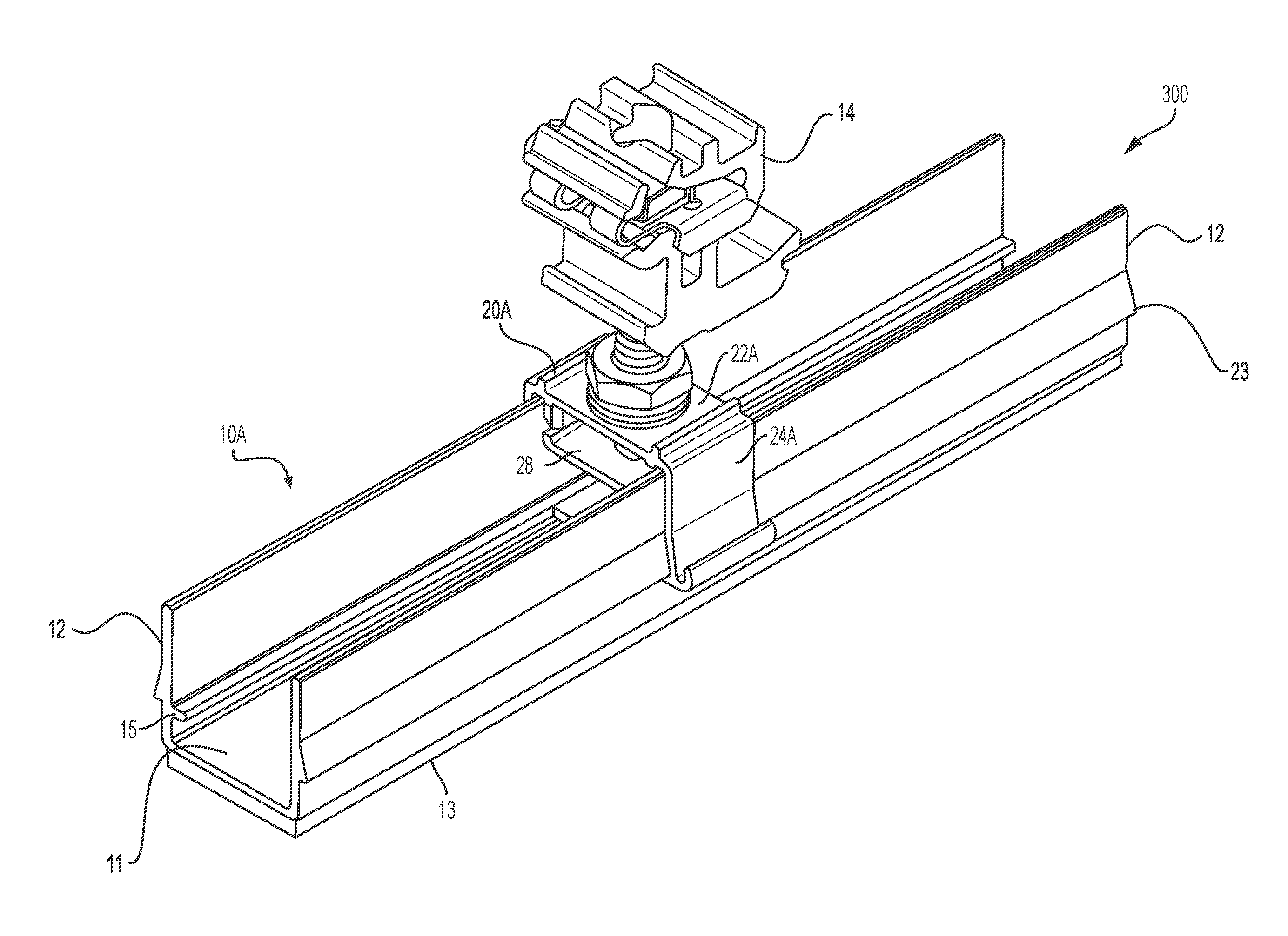
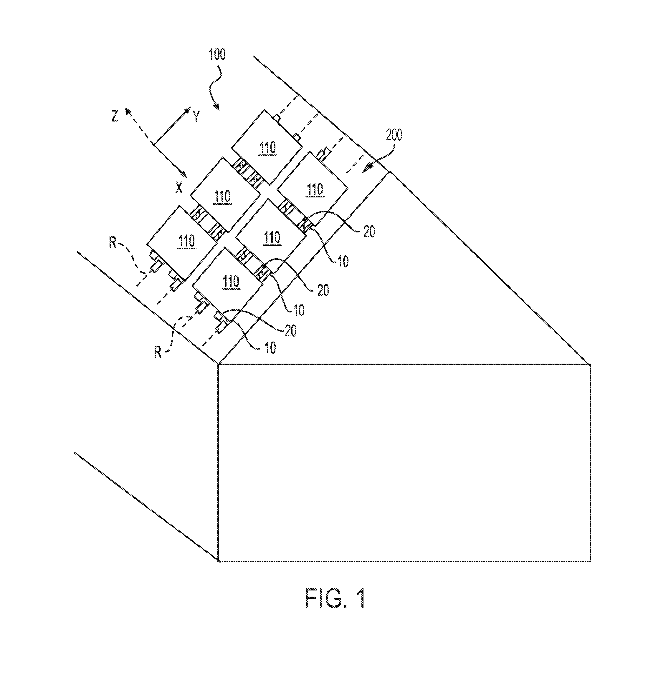
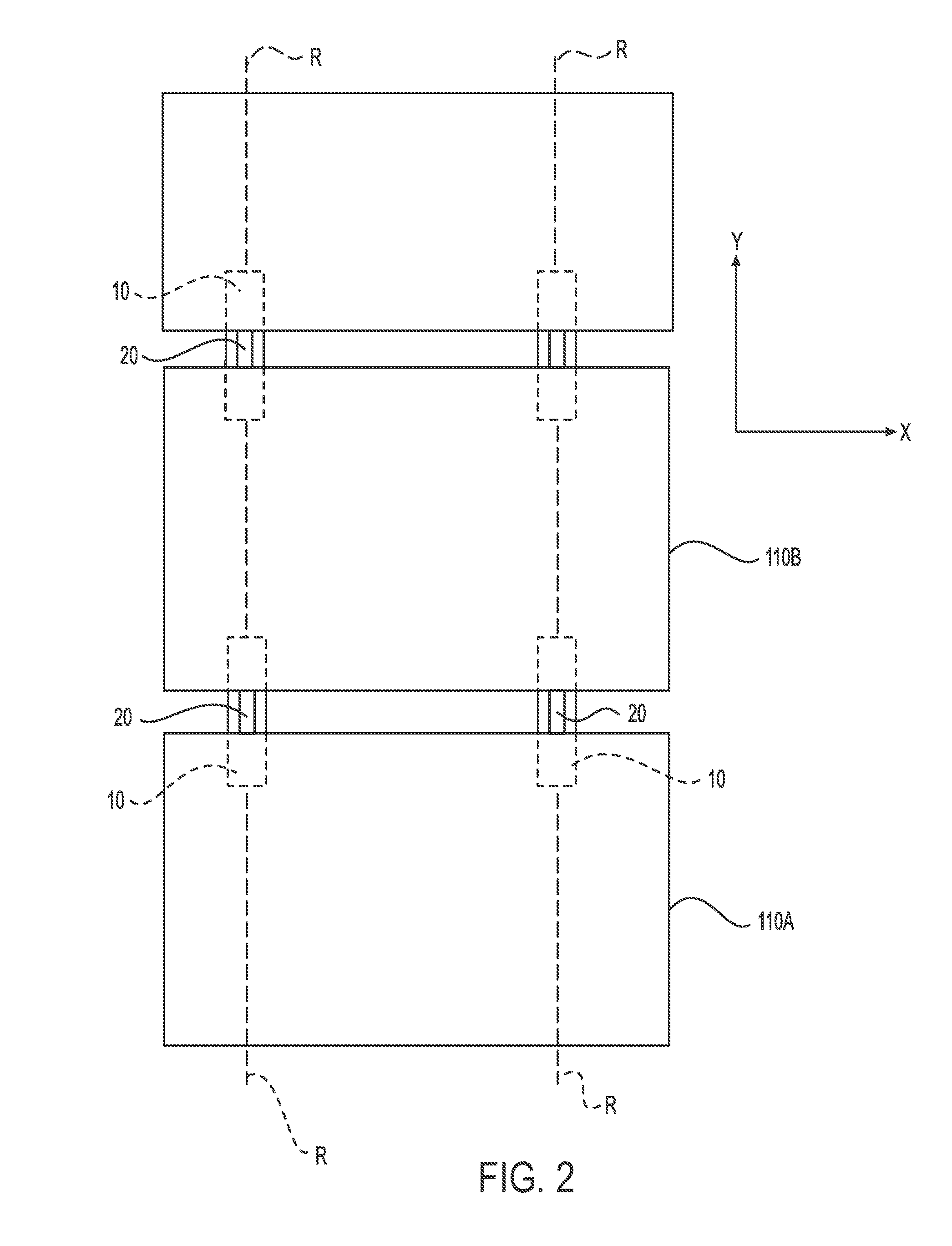
[0043]FIGS. 1 and 2 show a mounting system used to assemble a photovoltaic module array on a building roof, in accordance with an embodiment. Specifically, photovoltaic array 100 may be formed from individual photovoltaic modules 110. In accordance with some embodiments, the mounting system may include extruded base members 10 and coupling assemblies 20. Extruded base members 10 may be mounted onto roof 200. In some embodiments, extruded base members 10 may...


PUM


Abstract

Photovoltaic mounting systems and coupling assemblies for mounting photovoltaic modules are provided. The mounting systems may include short extruded base members that are mounted onto the supporting surface at approximate locations on the supporting surface, and coupling assemblies that may slide along the length of the base members during installation and be locked at particular positions on the length of the base members. The coupling assemblies may be coupled to connectors that in turn couple to two photovoltaic modules. In operation, the installer may first determine approximate locations on which to mount the base members and mount all required base members, and then, place the coupling assemblies at desired locations, lock the coupling assemblies at the desired locations, position the photovoltaic modules in the connectors of the coupling assemblies, and move to the next set of coupling assemblies.

Description

CROSS-REFERENCES TO RELATED APPLICATIONS[0001]This claims the benefit of U.S. Provisional Application No. 62 / 149,203, filed Apr. 17, 2015, the disclosure of which is incorporated herein by reference in its entirety for all purposes.FIELD OF THE INVENTION[0002]Embodiments of the present disclosure pertain to mounting systems for photovoltaic arrays.BACKGROUND[0003]Assembling photovoltaic arrays is typically a time consuming process. Improvements are therefore always desired to make array assembly faster, easier, and less expensive. By reducing the time taken to assemble the array, the overall system cost is reduced. Assembly and mounting of photovoltaic arrays typically requires precisely located mounting components used to affix the arrays to supporting structures such as the roof or roof rafters. In many installations, this may require significant time spent planning once at the installation site to determine particular locations for a variety of mounting components. When exact loc...

Claims


Application Information

Patent Timeline
Patent Type & Authority Applications(United States)
IPC IPC(8): H02S20/23
CPCH02S20/23Y02E10/47F24S25/33F24S25/636F24S25/70F24S2025/6004F24S2025/018Y02E10/50Y02B10/10Y02B10/20
Inventor MOLINA, DAVIDHUDSON, TYRUS
Owner TESLA INC
Why Eureka
Try Eureka