Measurement system using tracking-type laser interferometer and return method of the measurement system

a laser interferometer and measurement system technology, applied in the direction of measuring devices, instruments, electromagnetic wave reradiation, etc., can solve the problems of environmental changes and require additional hardware, and achieve the effect of eliminating human intervention, minimizing environmental changes, and simple methods

Inactive Publication Date: 2016-10-27
MITUTOYO CORP
View PDF2 Cites 3 Cited by
  • Summary
  • Abstract
  • Description
  • Claims
  • Application Information

AI Technical Summary

Benefits of technology

[0019]According to the present invention, even when tracking is no longer possible due to laser light from the tracking-type laser interferometer being interrupted, for example, tracking can be automatically reset and measurement can be restarted with a simple method, and without additional hardware. Therefore, a tracking return task can be automated, eliminating human intervention and therefore minimizing environmental changes, making possible more highly accurate and stable measurement.

Problems solved by technology

Because human beings are involved in this work, environmental changes (such as in temperature) may result.
However, both of these require additional hardware.

Method used


Image

  • Measurement system using tracking-type laser interferometer and return method of the measurement system
  • Measurement system using tracking-type laser interferometer and return method of the measurement system
  • Measurement system using tracking-type laser interferometer and return method of the measurement system

Examples


first embodiment

[0040]Hereafter, a return action of the measurement system shown in FIG. 2 is described with reference to FIG. 3.

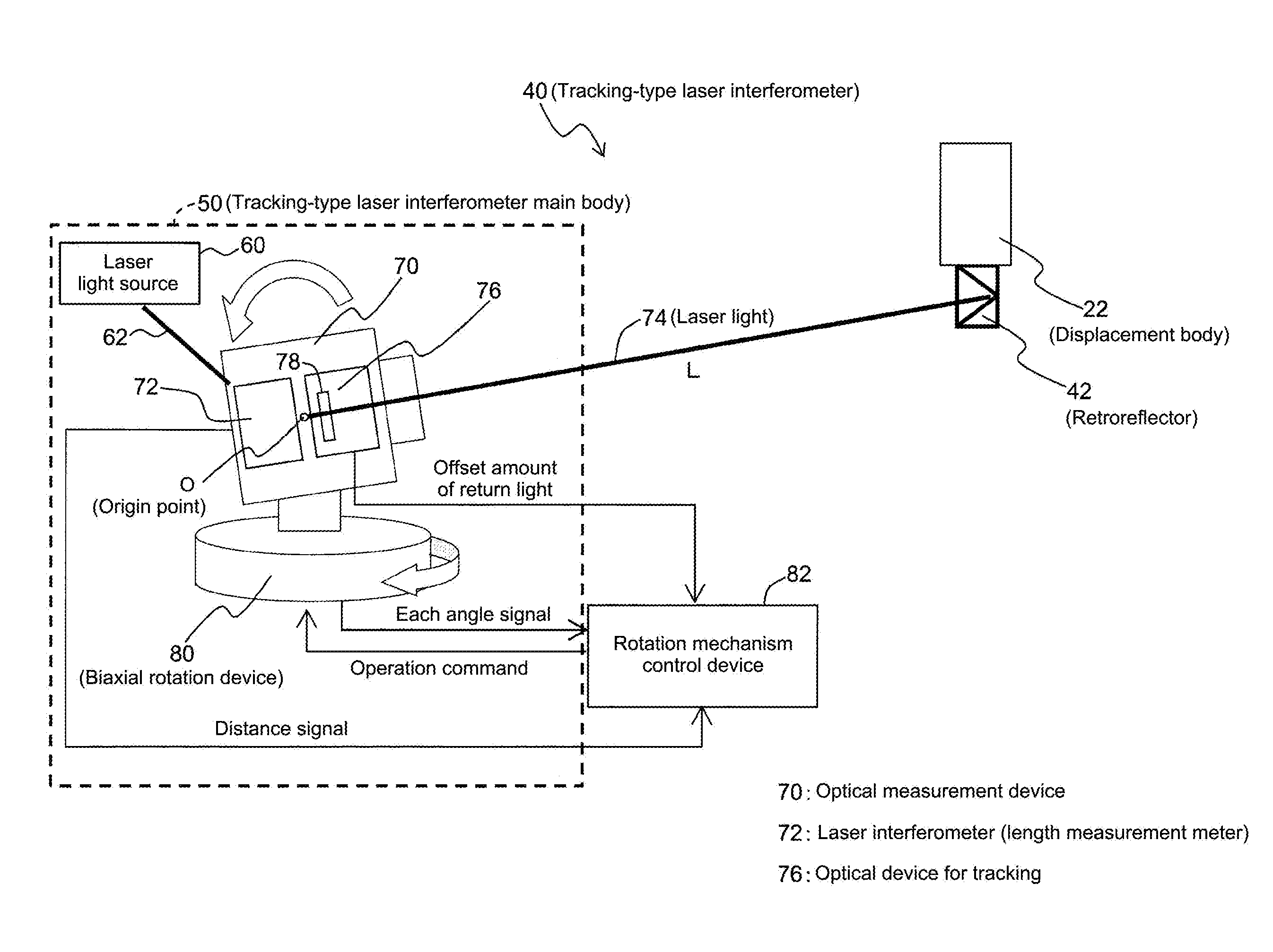
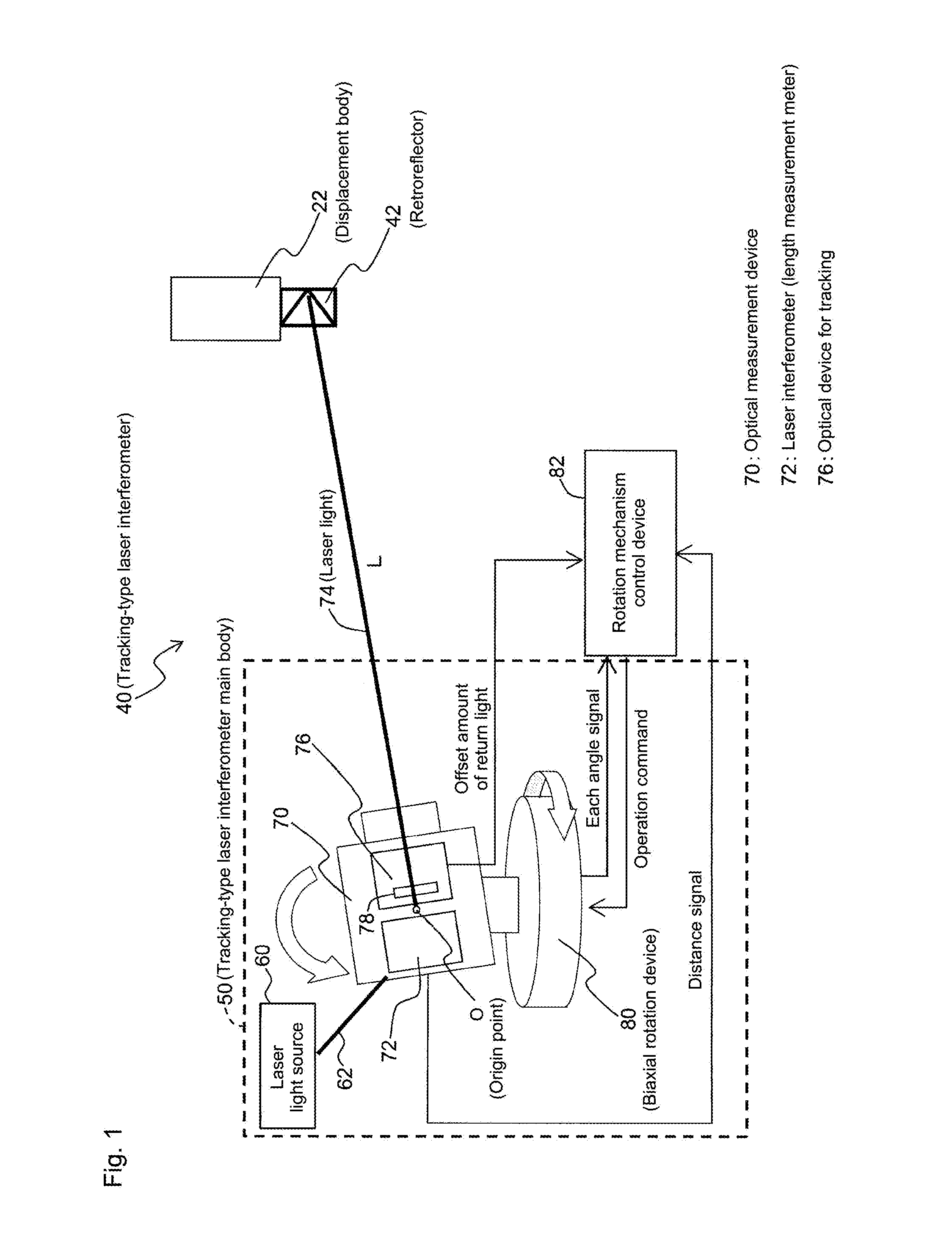
[0041]First, in step 100, laser light 74 is emitted toward the retroreflector 42 and the tracking-type laser interferometer 40 is placed in a tracking state.

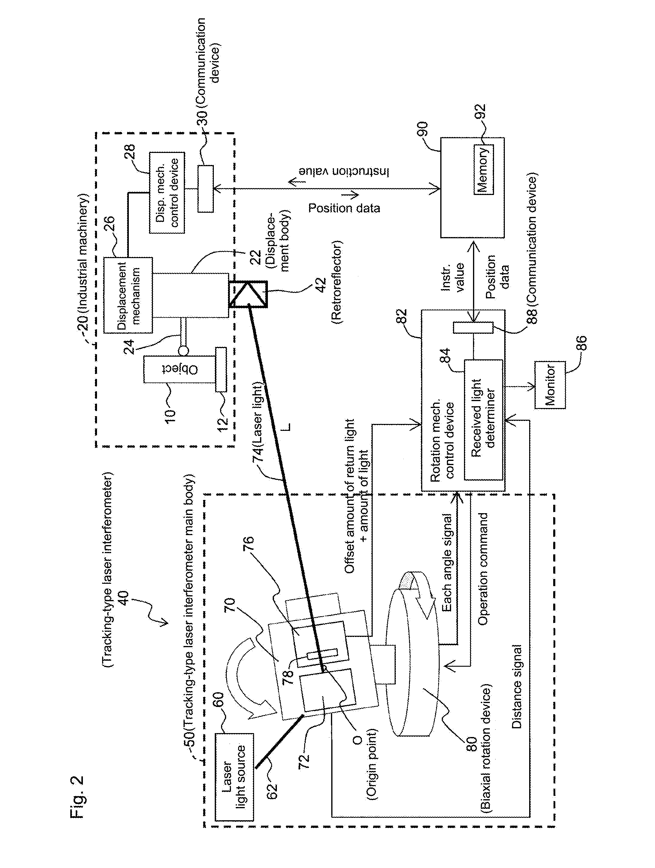
[0042]Next, in step 110, the displacement body 22 is displaced and, as shown in FIG. 4, data is collected at one desired point. A combination of position data from the industrial machinery 20 and rotation position data of the biaxial rotation device 80 from the tracking-type laser interferometer 40 at this point in time is stored in the memory 92 of the PC 90 as a return point 1. The return point 1 is defined where no obstacle is present in a movement range of the displacement body 22.

[0043]Next, advancing to step 120, the displacement body 22 is displaced to a predetermined measurement position and measurement is conducted. At this time, in step 130, a determination is made as to whether an amount of light received b...

second embodiment

[0047]Hereafter, the return action is described with reference to FIG. 5.

[0048]In step 100, which is similar to that of the first embodiment, laser light 74 is emitted toward the retroreflector 42 and the tracking-type laser interferometer 40 is placed in a tracking state.

[0049]Next, the process advances to step 112 and, as shown in FIG. 6, the displacement body 22 is displaced to a plurality of desired points, and a combination of position data for the displacement body 22 at this plurality of desired points and rotation position data of the biaxial rotation device 80 from the tracking-type laser interferometer 40 is stored in the memory 92 of the PC 90 as a plurality of return points 1 . . . N (in this example, N=2). The return points 1 and 2 are defined where no obstacle is present in the movement range of the displacement body 22.

[0050]Next, in step 120, the displacement body 22 is displaced to a predetermined measurement position, and when there is no abnormality in the amount ...


PUM


Abstract

When measurement is conducted using a measurement system utilizing a tracking-type laser interferometer, laser light is emitted at a retroreflector, the tracking-type laser interferometer is placed in a tracking state, and a displacement body is displaced to a desired point and a combination of position data of the displacement body at a single desired location and rotation position data of a biaxial rotation mechanism from the tracking-type laser interferometer is stored. When a received light determiner determines that there is an abnormality in an amount of light, the positions of the displacement body and the biaxial rotation mechanism are maintained, and the displacement body and biaxial rotation mechanism are displaced to the respective stored, predetermined positions. When the abnormality in the amount of received light is eliminated after displacement, the tracking-type laser interferometer is placed in the tracking state and measurement is restarted.

Description

CROSS-REFERENCE TO RELATED APPLICATIONS[0001]The present application claims priority under 35 U.S.C. §119 of Japanese Application No. 2015-086838, filed on Apr. 21, 2015, the disclosure of which is expressly incorporated by reference herein in its entirety.BACKGROUND OF THE INVENTION[0002]1. Field of the Invention[0003]The present invention relates to a measurement system using a tracking-type laser interferometer and a return method of the measurement system. In particular, the present invention relates to a measurement system using a tracking-type laser interferometer and a return method of the measurement system which, even when a laser light is interrupted and tracking is no longer possible, is capable of automatically resetting the tracking and restarting measurement.[0004]2. Description of Related Art[0005]Japanese Patent No. 2,603,429, U.S. Pat. No. 6,147,748, and Japanese Patent No. 4,776,454 describe examples of a tracking-type laser interferometer which, while tracking a d...

Claims


Application Information

Patent Timeline
Patent Type & Authority Applications(United States)
IPC IPC(8): G01S3/786G01B9/02G01B11/14
CPCG01S3/786G01B9/02041G01B11/14G01B9/02G01B11/04G01B21/04G01S17/36G01S17/66
Inventor TAKETOMI, NAOYUKI
Owner MITUTOYO CORP
Why Eureka
Try Eureka