
Telescopic saw

a telescopic saw and saw blade technology, applied in the field of telescopic saws, can solve the problems of cumbersome process, complex design of such conventional chainsaws, and inability to use battery-powered sawing tools,

Inactive Publication Date: 2016-11-03
GONZALES JOSEPH
View PDF54 Cites 18 Cited by
  • Summary
  • Abstract
  • Description
  • Claims
  • Application Information

AI Technical Summary

Benefits of technology

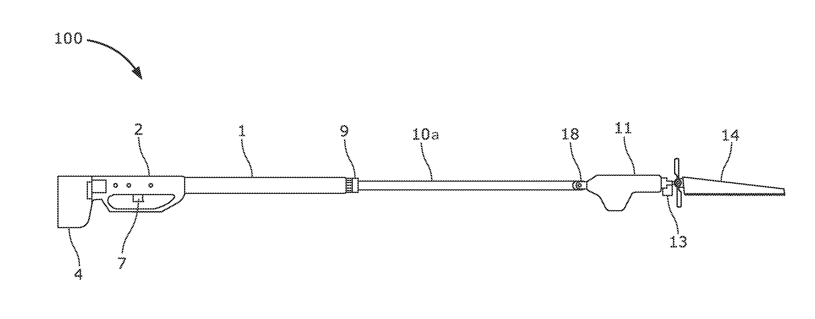
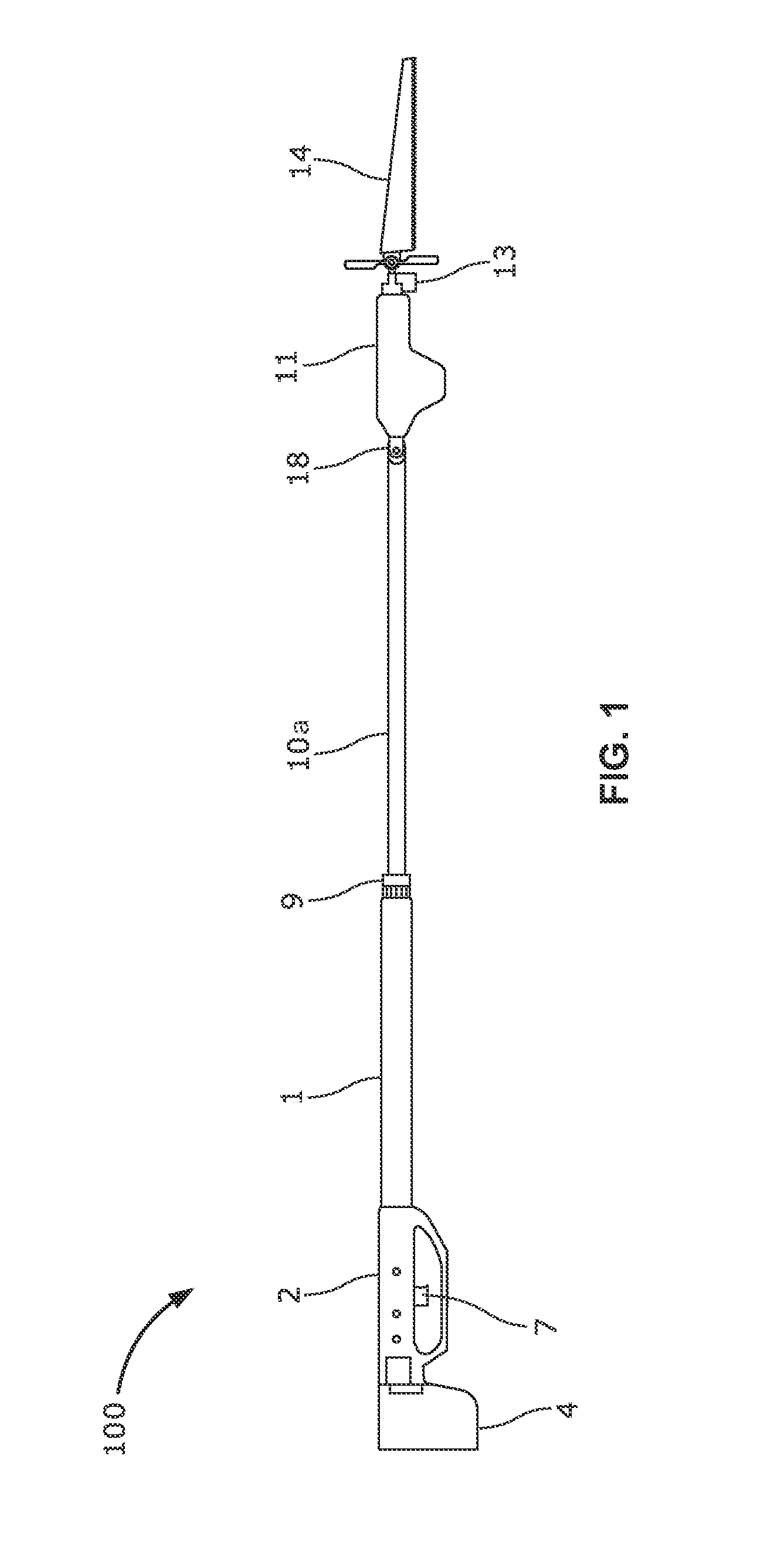
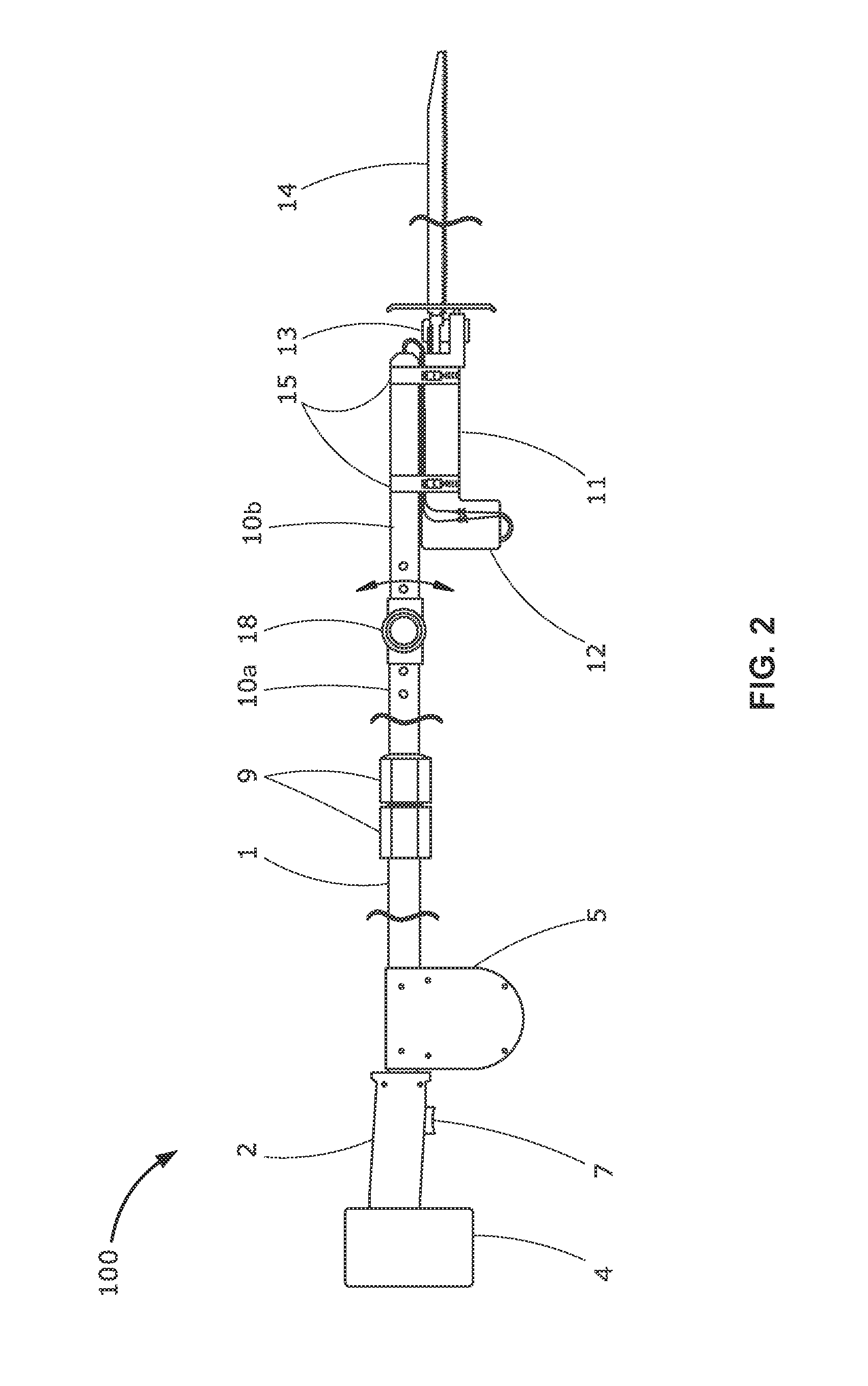
The telescopic saw is a tool designed to address issues in the field of forestry, such as the difficulty in safely and efficiently pruning trees at various angles. The telescopic saw features a handle with a battery, telescopic poles, an electric reciprocating saw holder with a blade, and a spring-loaded wire spool to actuate the blade. The telescopic poles are connected to each other and extend from the handle, with the electric reciprocating saw holder attached to the last telescopic pole. The saw blade is hingedly connected to the electric reciprocating saw holder and can sway along a predefined angle and prune an object when the power switch is actuated. The telescopic saw is designed to be easily and quickly attached to a tree and can safely and efficiently prune trees at various angles.

Problems solved by technology

The design of such conventional chainsaws is complicated and requires consistent maintenance to keep the chainsaws in working condition.
In case, if we need to use the chainsaw at a height, additional height increasing means are required to be added to the basic design of the chainsaw which is a cumbersome process.
Some battery powered sawing tools have no means of height increasing and use heavy chainsaw head, which requires same maintenance as gas powered tool.

Method used


Image

  • Telescopic saw
  • Telescopic saw
  • Telescopic saw

Examples


Embodiment Construction

[0014]FIG. 1 exemplarily illustrates a front perspective view of an embodiment of the telescopic saw 100, and FIG. 2 exemplarily illustrates a front perspective view of another embodiment of the telescopic saw 100. The telescopic saw 100 comprises a handle 2, a power switch 7, one or more telescopic poles 1, 10a and 10b, an electric reciprocating saw holder 11, and a saw blade 14. The handle 2 houses a battery 3 within a battery holder section 4 of the handle 2 as shown in FIG. 3, and the power switch 7 is positioned distally to the handle 2, and in communication with the battery 3. The telescopic poles 1, 10a and 10b are attached to each other and extending from the handle 2, where a last of the telescopic poles 10b is pivotally connected to the second last telescopic pole 10a. The electric reciprocating saw holder 11 is fastened to a distal end of the last telescopic pole 10b, where the electric reciprocating saw holder 11 holds the saw blade 14. The saw blade 14 is hingedly conne...


PUM

PropertyMeasurementUnit
timeaaaaaaaaaa
lengthaaaaaaaaaa
heightaaaaaaaaaa

Abstract

A telescopic saw includes a handle, a power switch, one or more telescopic poles, an electric reciprocating saw holder and a saw blade. The handle houses a battery within a holder section of the handle, and the power switch is positioned at a distal end of the handle, and in communication with the battery. The telescopic poles are attached to each other and extending from the handle, where a last of the telescopic poles is pivotally connected to the second last telescopic pole. The electric reciprocating saw holder is fastened to a distal end of the last telescopic pole, where the electric reciprocating saw holder holds the saw blade. The saw blade is hingedly connected to the electric reciprocating saw holder, where the saw blade sways along a predefined angle in horizontal direction, and reciprocate linearly to prune an object, when the power switch is actuated by a user.

Description

CROSS REFERENCE TO RELATED APPLICATIONS[0001]This application claims the benefit of provisional patent application No. 62 / 155,375, filed in the United States Patent and Trademark Office on Apr. 30, 2015. The specification of the above referenced patent application is incorporated herein by reference in its entirety.BACKGROUND[0002]There are different types of sawing mechanisms widely used around the world. The most commonly used one is the conventional chainsaw, which includes a saw blade built into a chain. Generally, the chain is bound around an elongated metal guide bar, and driven by a small, single cylinder gasoline engine. The chain runs around sprockets, such as gear wheels, considered to turn continuously with teeth made from a hardened steel alloy mounted along its intervals. Within the engine, as the piston reciprocates back and forth inside the cylinder, and it pushes a connecting rod which turns a crankshaft. The crankshaft turns gears that are coupled through a centrifu...

Claims


Application Information

Patent Timeline
Patent Type & Authority Applications(United States)
IPC IPC(8): B25G1/04B23D49/16A01G3/08
CPCB25G1/04B23D49/16A01G3/085
Inventor GONZALES, JOSEPH
Owner GONZALES JOSEPH
Learn More