Miniature projecting device

a projecting device and miniature technology, applied in projectors, instruments, mountings, etc., can solve the problems of inconvenient dustproof design, affecting image display quality, and the development of miniature projecting devices is still in its infancy, so as to achieve lower dustproof levels, the effect of restricting the development of the functions of the miniature projecting devi

Active Publication Date: 2016-11-03
BEIJING PICO TECH
View PDF30 Cites 16 Cited by
  • Summary
  • Abstract
  • Description
  • Claims
  • Application Information

AI Technical Summary

Benefits of technology

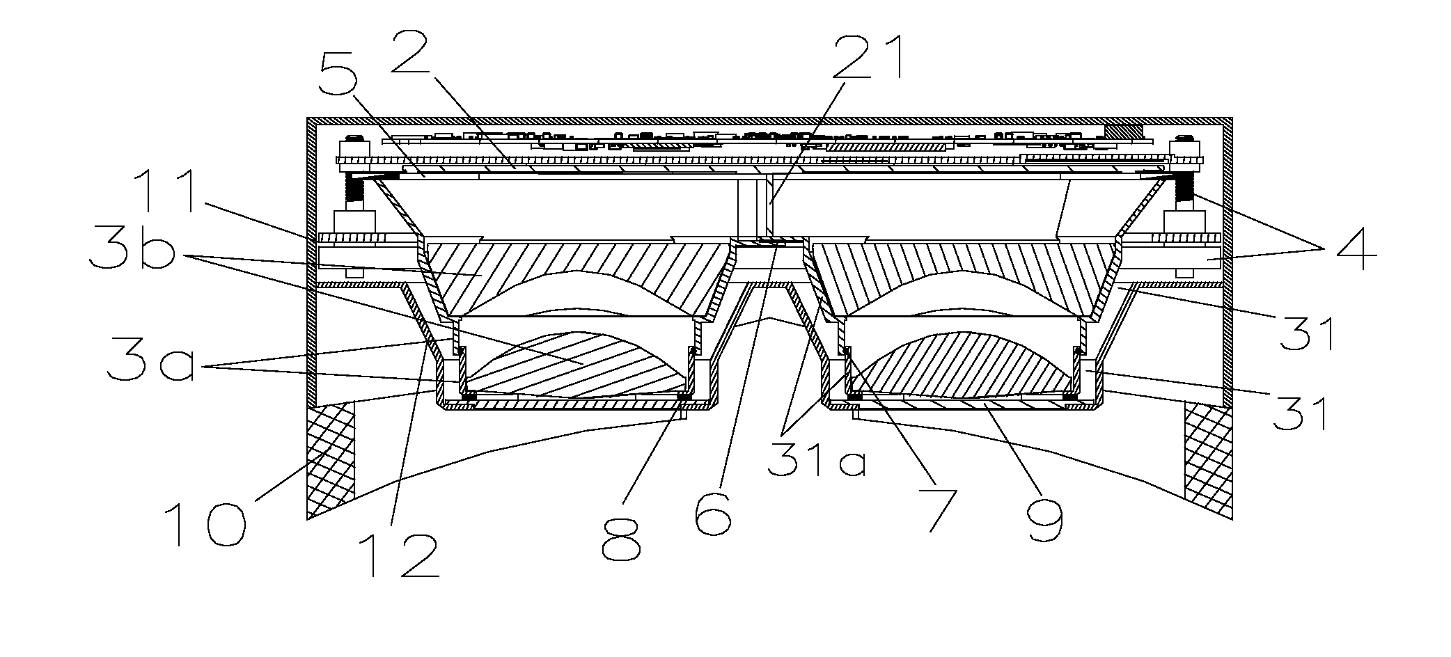
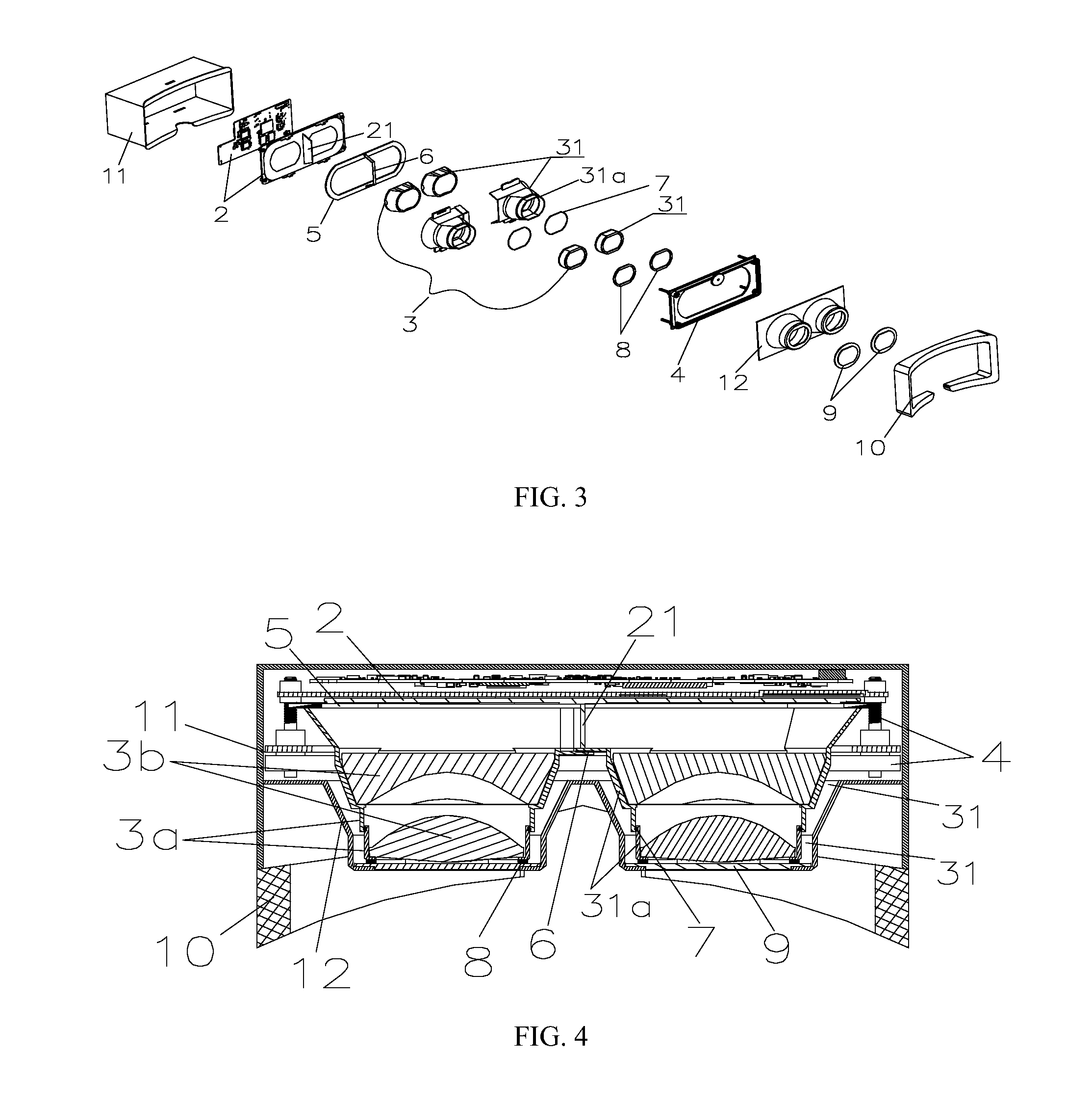
[0017]The inventor(s) of the present invention find(s) that most miniature projecting devices of the prior arts have lower dustproof levels, and dustproof designs are basically limited to the housings so that development of the functions of the miniature projecting devices is restricted. Therefore, the technical problem to be solved by the present invention is not anticipated by those skilled in the art, and the present invention includes novel technical solutions. By forming a dustproof structure that can package the lens and the corresponding display region in a sealed space enclosed by the lens barrel, the window and the display module, the present invention can effectively protect the optical display system of the miniature projecting device against pollution of dust. The dustproof structure of the present invention has a higher dustproof level and will not be affected by the housing provided with various openings.

Problems solved by technology

Optical display systems are very sensitive to dust and pollution of optical display systems will affect the image display quality.
However, development of miniature projecting devices is still in its infancy, with current dustproof designs focusing on sealing of the housings and packaging of the optical display systems in the housings.
Such dustproof designs are not conducive for heat dissipation and diopter and interpupillary distance adjustment typically require openings to be provided to the housing, interfering with this sealing.

Method used


Image

  • Miniature projecting device
  • Miniature projecting device
  • Miniature projecting device

Examples


Embodiment Construction

[0031]Now, various embodiments of this invention will be described in detail with reference to the drawings. It should be noted that, unless specified otherwise, the arrangements of the members and steps, the mathematical formulas and numerical values described in these embodiments do not restrict the scope of the invention.

[0032]The following descriptions for at least one embodiment are actually descriptive only, and shall not be intended to limit the invention and any application or use thereof.

[0033]The techniques, methods and devices well known to those skilled in the related arts may not be discussed in detail. However, where applicable, such techniques, methods and devices should be deemed a part of the description.

[0034]Any specific value shown herein and in all the examples should be interpreted as illustrative only rather than restrictive. Therefore, other examples of the embodiments may include different values.

[0035]It should be noted that similar signs and letters in the...


PUM


Abstract

The present disclosure discloses a miniature projecting device comprising a housing and a display module having a lens module inside it, wherein the lens module comprises a lens barrel and a lens inside it. A front dustproof cushion is sandwiched between the lens barrel front opening edge and the display module display region frame and a rear dustproof cushion is sandwiched between the lens barrel rear opening edge and the housing window such that the lens is packaged in a sealed space enclosed by the lens barrel. The window, the display module and a display region of the display module are located in the sealed space. The dustproof structure of the miniature projecting device has a high dustproof level without being affected by various openings on the housing.

Description

RELATED APPLICATIONS[0001]This application claims the benefit of CN21510213292.1, filed Apr. 29, 2015. This application is herein incorporated by reference in its entirety for all purposes.FIELD OF THE INVENTION[0002]The present invention relates to the field of projection and display techniques, and particularly to a dustproof structure of a miniature projecting device.BACKGROUND OF THE INVENTION[0003]Miniature projecting devices, which are also commonly referred to as portable projecting devices or pocket type projecting devices, are used for displaying images and colors. The core structure of a miniature projecting device is an optical display system including a display module and a lens module. Optical display systems are very sensitive to dust and pollution of optical display systems will affect the image display quality. A miniature projecting device will fail to function normally if such pollution reaches a certain degree, making dustproof designs for miniature projecting dev...

Claims


Application Information

Patent Timeline
Patent Type & Authority Applications(United States)
IPC IPC(8): G02B27/00G03B21/10G02B27/01G03B21/14
CPCG02B27/0006G02B27/0172G03B21/10G03B21/145G02B7/12G02B27/017G02B2027/0154G02B27/0176
Inventor ZHANG, FENG
Owner BEIJING PICO TECH
Why Eureka
Try Eureka