[0037] The embodiments of the technical solution of the present invention will be described in detail below in conjunction with the accompanying drawings. The following embodiments are only used to explain the technical solutions of the present invention more clearly, and therefore are only used as examples, and cannot be used to limit the protection scope of the present invention.
[0038] It should be noted that, unless otherwise specified, the technical or scientific terms used in this application shall have the usual meaning understood by those skilled in the art to which the present invention belongs.
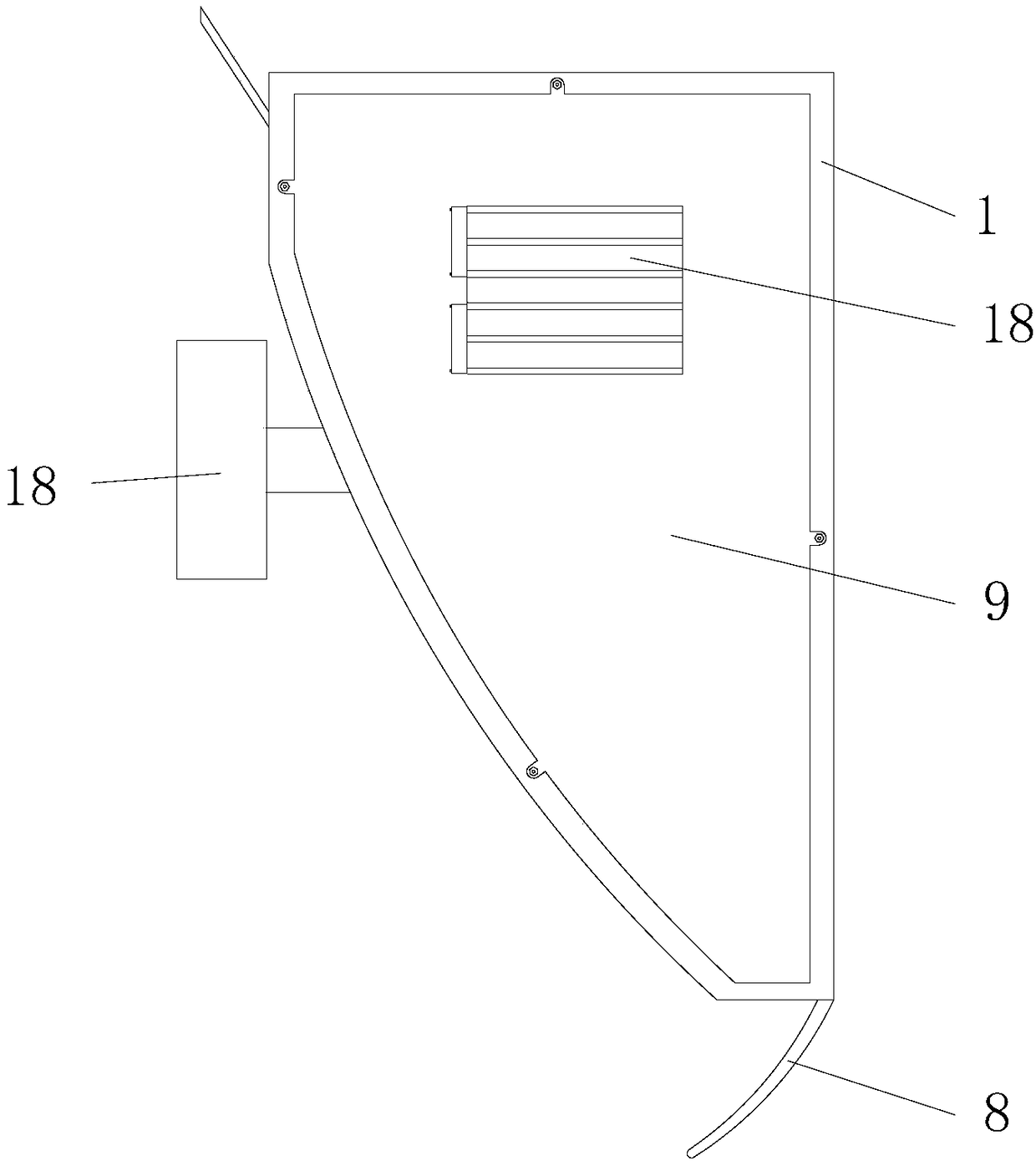
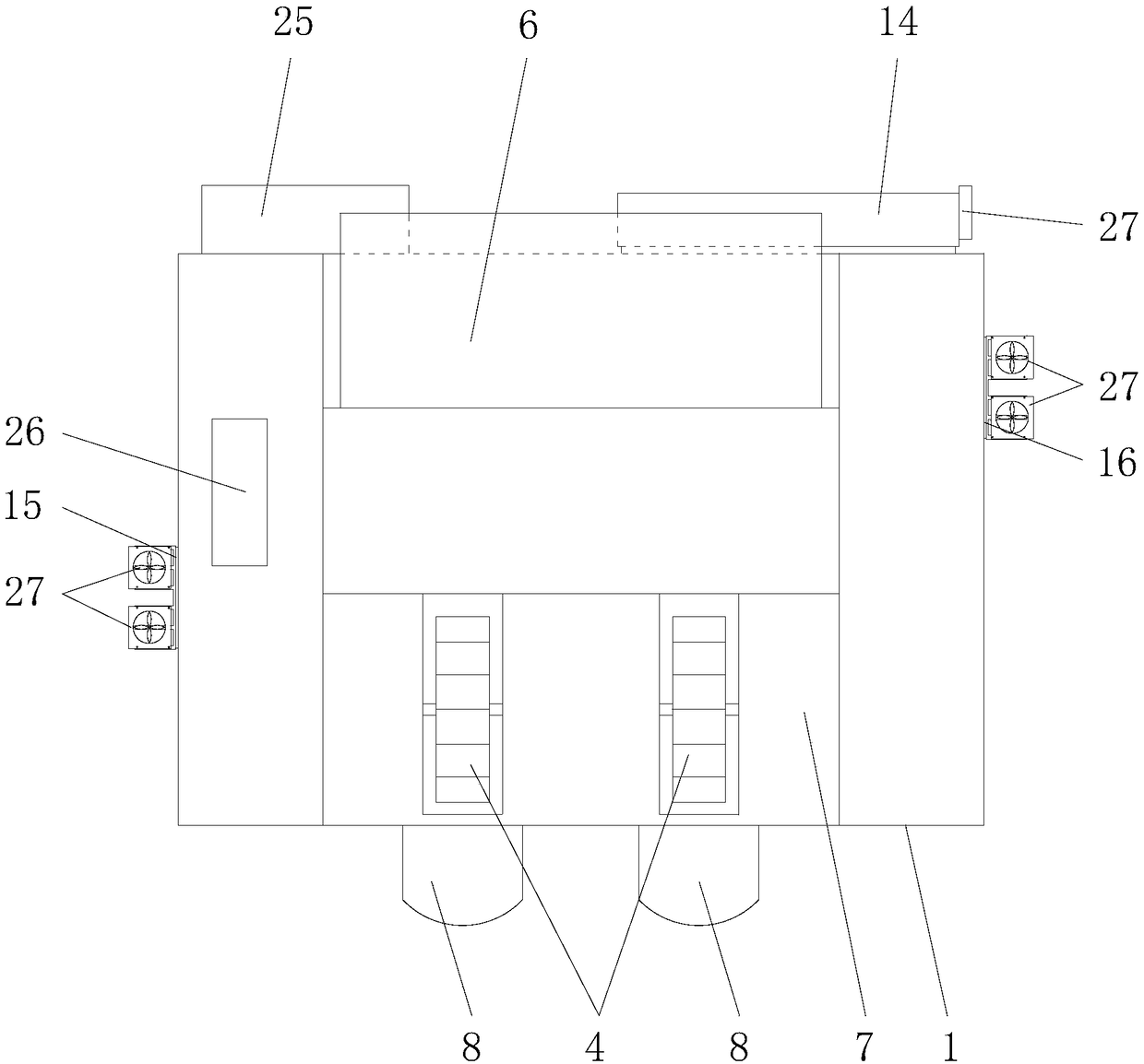
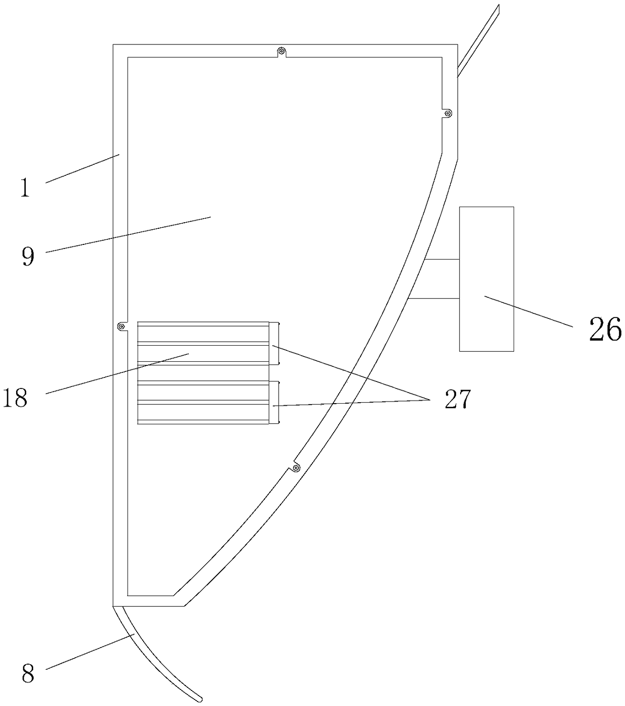
[0039] Such as figure 1 As shown, this embodiment provides a currency detector for finance, including a housing 1, a first motor 2, a second motor 3, a banknote receiving wheel 4, and a driving wheel 5; the driving wheel 5 and the banknote receiving wheel The wheels 4 are respectively installed in the upper opening 6 and the lower opening 7 of the casing 1, the first motor 2 and the second motor 3 are both installed in the casing 1, and the first motor 2 is in transmission connection with the driving wheel 5. , And the second motor 3 is in transmission connection with the banknote receiving wheel 4. Wherein, the lower opening 7 is also provided with a banknote baffle 8 and a display 26 is provided on the housing.
[0040] Such as figure 2 with image 3 As shown, in order to avoid the problem that dust in the environment is easy to accumulate inside the housing 1, and even sundries are easy to enter from the heat dissipation port, in this embodiment, the front side wall, left side wall and right side wall of the housing 1 are all provided There is a detachable cover plate 9 which is connected to the corresponding side wall by screws, and the front side wall, the left side wall and the right side wall are all provided with the corresponding sink groove 10 and screw holes 11 in the cover plate 9. Each cover plate 9 is fully sealed with no heat dissipation holes, which effectively prevents dust in the air from entering the housing 1, avoiding long-term accumulation of dust from affecting the heat dissipation performance and causing circuit failures, and improving the dustproof level.
[0041] Such as Figure 4 to Figure 10 As shown, since the housing 1 is fully sealed, in order to solve the problem of poor heat dissipation of the first motor 2 and the second motor 3 inside the housing 1, which may cause the motor to burn easily, this embodiment also includes a first heat conducting member 12, The second heat-conducting member 13, the first heat dissipation mechanism 14 and the second heat dissipation mechanism 15. The first heat dissipation mechanism 14 and the second heat dissipation mechanism 15 each include a semiconductor refrigeration fin 17 and a heat dissipation fin 18. The semiconductor refrigeration of the first heat dissipation mechanism 14 The sheet 17 is installed on the rear side wall of the casing 1, the semiconductor refrigeration sheet 17 of the second heat dissipation mechanism 15 is installed on the left side wall of the casing 1, and the semiconductor refrigeration sheet 17 of the first heat dissipation mechanism 14 and the second heat dissipation mechanism 15 The cold surfaces of the cooling fins 17 are all located in the housing 1, and the hot surfaces of the semiconductor cooling fins 17 of the first heat dissipation mechanism 14 and the second heat dissipation mechanism 15 are all located outside the housing 1. The heat sink 18 of the first heat dissipation mechanism 14 It is installed on the hot surface of the peltier fin 17 of the first heat dissipation mechanism 14, and the fin 18 of the second radiator mechanism 15 is installed on the hot surface of the peltier fin 17 of the second heat dissipation mechanism 15. The first heat-conducting member 12 includes a first cylindrical body 19 and a first heat-conducting body 20. The first cylindrical body 19 is sleeved on the outer surface of the first motor 2 for absorbing the emission from the first motor 2 The first heat conductor 20 is fixedly connected to the first cylindrical body 19, and the first heat conductor 20 is in contact with the cold surface of the semiconductor refrigeration fin 17 of the first heat dissipation mechanism 14. The second heat conductor 22 includes a second cylindrical body 21 and a second heat conductor 22. The second cylindrical body 21 is sleeved on the outer surface of the second motor 3 for absorbing the emission from the second motor 3 The second heat conductor 22 and the second cylindrical body 21 are fixedly connected, and the second heat conductor 22 is in contact with the cold surface of the second heat dissipation mechanism 15 of the semiconductor refrigeration fin 17.
[0042] The first heat-conducting member 12 and the second heat-conducting member 13 are used to quickly transfer the heat of the first motor 2 and the second motor 3 to the corresponding first heat dissipation mechanism 14 and the second heat dissipation mechanism 15, while the first heat dissipation mechanism 14 and the second heat dissipation mechanism 14 The heat dissipation mechanism 15 uses the cold surface of the semiconductor refrigeration fin 17 to absorb and transfer the heat of the first motor 2 and the second motor 3 to the hot surface, which is actually to quickly transfer the heat of the first motor 2 and the second motor 3 to the housing 1External. Even if the device is continuously working for a long time, it can effectively transfer the heat of the first motor 2 and the second motor 3 to the outside of the casing 1, avoiding the heat from the first motor 2 and the second motor 3. It can be damaged by collecting at different locations, thereby greatly improving the heat dissipation performance, reducing the probability of the first motor 2 and the second motor 3 being burned out, and improving the safety level.
[0043] To further improve the heat dissipation performance, the first cylindrical body 19 and the first heat conductor 20 in this embodiment are integrally formed, and the material is copper. The second cylindrical body 21 and the second heat conductor 22 are integrally formed, and the material is copper. Copper has a high thermal conductivity, which can quickly absorb the heat of the first motor 2 and the second motor 3, which greatly improves the heat dissipation performance. In addition, the semiconductor refrigeration fin 17 of the first heat dissipation mechanism 14 is opposite to the first motor 2. Reducing the distance between the semiconductor refrigeration fin 17 of the first heat dissipation mechanism 14 and the first motor 2 is beneficial to shorten the length of the first heat conductor 20 and further improve the heat dissipation performance of the first motor 2.
[0044] Since the power of the semiconductor refrigeration fin 17 is relatively large, in order to save electric energy, under the premise of ensuring the normal operation of the first motor 2 and the second motor 3, this embodiment further includes a third heat dissipation mechanism 16 which includes The semiconductor refrigeration fin 17 and the heat sink 18; the semiconductor refrigeration fin 17 of the third heat dissipation mechanism 16 is installed on the right side wall of the housing 1, and the cold surface of the semiconductor refrigeration fin 17 is located in the housing 1, and the hot surface is located in the housing Outside the body 1; the third heat dissipation mechanism 16 has two heat sinks 18, which are respectively attached to the cold surface and the hot surface of the semiconductor cooling fin 17 of the third heat dissipation mechanism 16. The third heat dissipation mechanism 16 is an auxiliary heat dissipation mechanism. The first heat dissipation mechanism 14 and the second heat dissipation mechanism 15 take away most of the heat of the first motor 2 and the second motor 3, and the third heat dissipation mechanism 16 absorbs the remaining heat in the housing 1. A small part of the heat, which mainly comes from the electronic components, further reduces the temperature in the housing 1.
[0045] Such as Figure 5 As shown, further, between the semiconductor refrigeration fin 17 of the first heat dissipation mechanism 14 and its heat sink 18, between the semiconductor refrigeration fin 17 of the second heat dissipation mechanism 15 and its heat sink 18, and the third heat dissipation mechanism Thermally conductive silica gel 23 is provided between the semiconductor refrigeration fin 17 and the heat sink 18 of the mechanism 16. The thermally conductive silica gel 23 has high thermal conductivity, excellent thermal conductivity, good electrical insulation, wide use temperature, good use stability, and can improve the heat transfer between the semiconductor refrigeration fin 17 and the heat sink 18 thereof. In addition, the thermally conductive silica gel 23 can also bridge the process tolerances on the structure and reduce the process tolerance requirements between the semiconductor refrigeration fin 17 and the heat sink 18. The heat sink 18 of the first heat dissipation mechanism 14, the heat dissipation fin 18 of the second heat dissipation mechanism 15, and the heat dissipation fin 18 of the third heat dissipation mechanism 16 are each provided with two fans 27. The fan 27 improves the heat dissipation capacity of the heat sink 18, spreads heat to the surrounding air in time, and cools the heat sink 18 in time.
[0046] In this embodiment, the semiconductor refrigeration fins 17 of the first heat dissipation mechanism 14, the semiconductor refrigeration fins 17 of the second heat dissipation mechanism 15, and the semiconductor refrigeration fins 17 of the third heat dissipation mechanism 16 are inlaid in the corresponding cover 9 in a one-to-one correspondence. . A heat insulation frame 24 is also provided between the semiconductor refrigeration fin 17 and the cover plate 9 to avoid excessive heat transfer between the inside and outside of the housing 1 and affect the heat dissipation performance.
[0047] This embodiment also includes a controller 25 installed on the outer surface of the rear side wall, and the output end of the controller 25 is respectively connected to the semiconductor refrigeration fin 17 of the first heat dissipation mechanism 14, and the second heat dissipation mechanism The semiconductor refrigeration fins 17 of the mechanism 15, the semiconductor refrigeration fins 17 of the third heat dissipation mechanism 16, and all the fans 27 are electrically connected. The first heat-conducting member 12 and the second heat-conducting member 13 are both provided with temperature sensors 28, and the two temperature sensors 28 are electrically connected to the input terminals of the controller 25, respectively. The controller 25 is a PLC controller 25, and the controller 25 sets two modes. The two temperature sensors 28 feed back the temperature of the first motor 2 and the second motor 3 to the controller 25 in real time, and the controller 25 automatically determines which mode to start based on the feedback temperature. One is the normal heat dissipation mode. In this mode, the controller 25 disables the third heat dissipation mechanism 16, the first heat dissipation mechanism 14, and the second heat dissipation mechanism 15. This mode is used when the frequency of use is not high. The other mode is the rapid heat dissipation mode. In this mode, the controller 25 causes the first heat dissipation mechanism 14, the second heat dissipation mechanism 15 and the third heat dissipation mechanism 16 to work simultaneously to quickly reduce the heat of the first motor 2 and the second motor 3. Cool out. The above two modes are automatically judged by the controller 25, the normal heat dissipation mode saves power, and the rapid heat dissipation mode ensures the heat dissipation performance.
[0048] Finally, it should be noted that the above embodiments are only used to illustrate the technical solutions of the present invention, but not to limit them; although the present invention has been described in detail with reference to the foregoing embodiments, those of ordinary skill in the art should understand: It is still possible to modify the technical solutions described in the foregoing embodiments, or equivalently replace some or all of the technical features; and these modifications or replacements do not make the essence of the corresponding technical solutions deviate from the technical solutions of the embodiments of the present invention. The scope shall be covered by the scope of the claims and specification of the present invention.