Anti-wind/Anti-wrapping assembly for trimmers

a technology of anti-wind and anti-wrapping, which is applied in the direction of mowers, agriculture tools and machines, and agriculture, and achieves the effects of winding and wrapping, low friction, and limited heat buildup

Active Publication Date: 2016-11-17
AERO FLEX TECH
View PDF16 Cites 13 Cited by
  • Summary
  • Abstract
  • Description
  • Claims
  • Application Information

AI Technical Summary

Benefits of technology

[0014]It has been discovered that winding and wrapping can be substantially mitigated by shielding the gaps that pinch the debris and by isolating the power sources of rotation that create the winding. The device of the preferred embodiments utilizes a roller, ball or sleeve bearing or the like or a simple collar that separates or isolates the rotating head from a strand or bundle of accumulated debris. The collar or the outer race or outer surface of the bearing is free to rotate, and power to the strand is thus disconnected, therefore enabling the strand of vegetation or debris to remain in a more static condition. The free floating collar is preferably made from lightweight material of low friction. It slides at a speed much lower than the rotating parts along the rotating surfaces with limited heat buildup. Gravity allows the collar to drop onto the rotating head below and to remain in a free-floating position. Further, it is confined by internal flange and radial clearances not to be able to transmit power. Even if some winding were to occur, the winding is prevented from being wound tightly enabling easy removal. A shield associated with the bearing or collar further serves to minimize or reduce exposure to pinching gaps between the bearing / collar and the trimmer head as well as between the bearing / collar and adjacent trimmer components. The shield may also serve as a locating guide for the application of the collar without bearings. Essentially, the shield minimizes the direct horizontal entry of fibrous matter into the likely pinching gaps that are also under rotational power. The shield may be positioned inward or outward but is more preferably positioned on the outward side of a gap containing a power winding exposure.

Problems solved by technology

Further, it is confined by internal flange and radial clearances not to be able to transmit power.

Method used


Image

  • Anti-wind/Anti-wrapping assembly for trimmers
  • Anti-wind/Anti-wrapping assembly for trimmers
  • Anti-wind/Anti-wrapping assembly for trimmers

Examples


Embodiment Construction

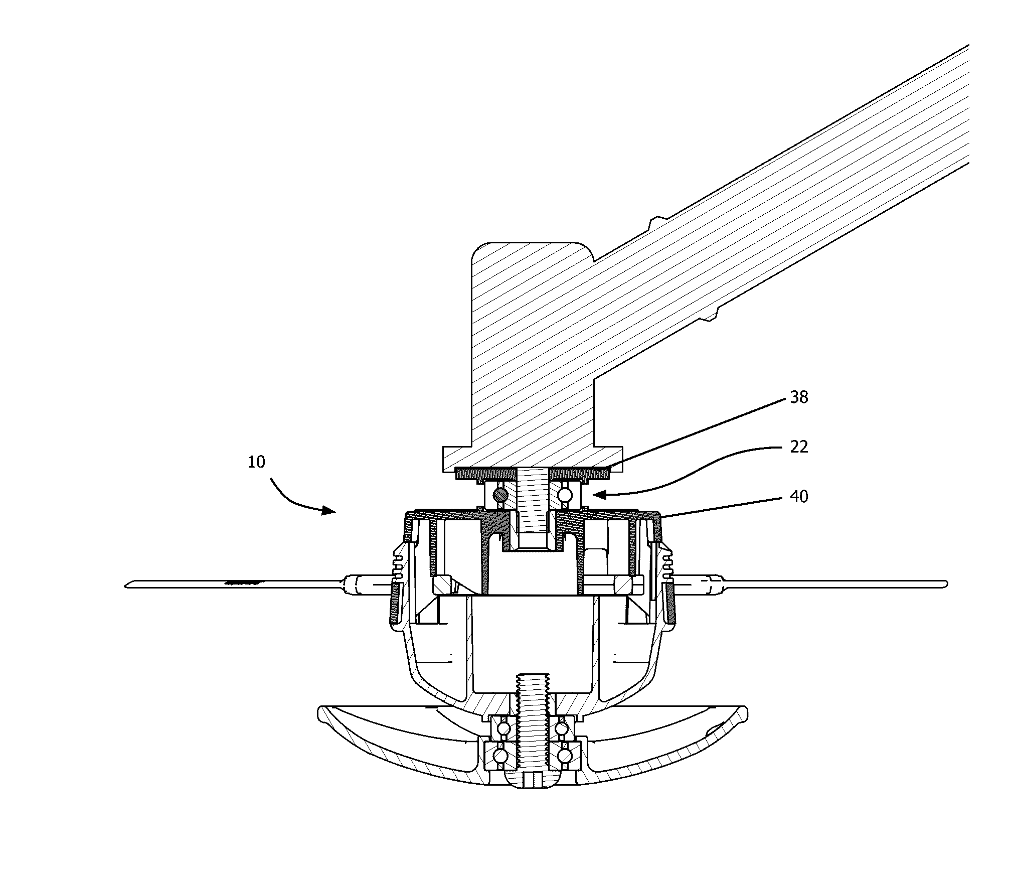
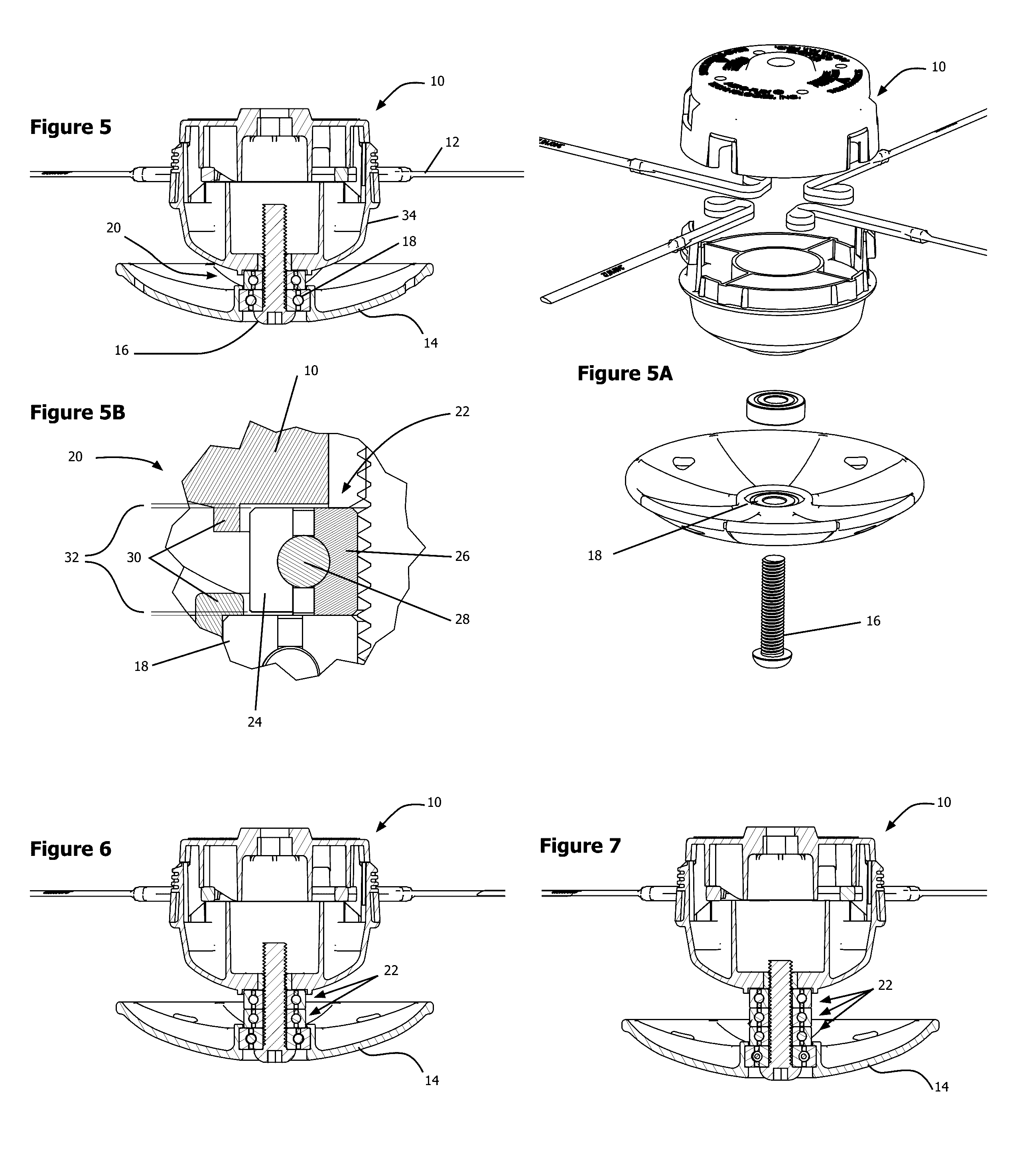
[0029]With reference to FIGS. 5-7, a first exemplary application of the anti-winding assembly will be described in conjunction with a trimmer that incorporates a glider disk such as the glider disk described in the noted co-pending U.S. patent application. A trimmer head 10 is typically secured to a rotatable arbor (not shown in FIG. 5) and supports one or more cutting lines 12. The cutting lines 12 shown in the figures are exemplary molded lines with aerodynamic cross-sections available from Aero-Flex Technologies of Rock Hill, S.C. The cutting lines may also be common monofilament cutting line.

[0030]The glider disk 14 is attached to the trimmer head 10 via a bolt 16 or the like through a glider bearing 18. The anti-winding assembly 20 is positioned in the gap between the glider disk 14 and the trimmer head 10.

[0031]The anti-winding assembly 20 includes a bearing 22 positionable between the trimmer head 10 and the glider disk 14. The bearing includes a freely rotating outer race 24...


PUM


Abstract

An anti-winding assembly reduces or prevents debris from winding on a trimmer and/or makes them easier to remove. The trimmer includes a trimmer head mounted to a rotatable arbor and supporting one or more cutting lines. The anti-winding assembly includes a collar positionable between the trimmer head and an adjacent trimmer component, and a shield positioned radially outward of the collar. The shield covers gaps between the collar and the trimmer head and between the collar and the adjacent trimmer component. The assembly reduces exposure to pinching gaps and to powered rotating parts that enable tight windings that can accumulate to lock trimmer rotation.

Description

CROSS-REFERENCES TO RELATED APPLICATIONS[0001]This application is a continuation-in-part (CIP) of U.S. patent application Ser. No. 14 / 955,196, filed Dec. 1, 2015, pending, which claims the benefit of U.S. Provisional Patent Application No. 62 / 085,983, filed Dec. 1, 2014, the entire contents of each of which are hereby incorporated by reference in this application.STATEMENT REGARDING FEDERALLY SPONSORED RESEARCH OR DEVELOPMENT[0002](NOT APPLICABLE)BACKGROUND OF THE INVENTION[0003]The invention relates to flexible line trimmers and brush cutters and, more particularly, to an anti-wind / wrapping assembly that prevents trimmed debris from winding on a trimmer.[0004]One of the most irritating experiences when cutting into higher or taller vegetation with a common flexible line trimmer or brush cutter is the wrapping of long strands of vegetation around the axis of rotation of the rotating head. It also applies to vines, or previously cut vegetation lying on the ground. Additionally, it is...

Claims


Application Information

Patent Timeline
Patent Type & Authority Applications(United States)
IPC IPC(8): A01D34/416
CPCA01D34/4167A01D34/4165
Inventor MORABIT, VINCENT D.
Owner AERO FLEX TECH
Why Eureka
Try Eureka