In-vehicle device covering structure

Inactive Publication Date: 2016-11-17
SUZUKI MOTOR CO LTD
View PDF10 Cites 1 Cited by
  • Summary
  • Abstract
  • Description
  • Claims
  • Application Information

AI Technical Summary

Benefits of technology

[0010]It is preferable that a rear portion of the in-vehicle device is recessed upward and forms a space, and the second attachment surface of the bracket overlaps the space when viewed from a vehicle lateral side. With this configuration, the distance that is set between the in-vehicle device and the second attachment surface of the bracket is within the range of the above-described space. Therefore, it is not necessary to provide this distance under the in-vehicle device, and thus, the cover can be located directly under the in-vehicle device, and thus the vehicle interior space is not reduced.
[0011]It is preferable that both ends of the second attachment surface of the bracket in a vehicle width direction are located inward, with respect to the vehicle width direction, of both ends of the in-vehicle device in the vehicle width direction. That is to say, when viewed in the vehicle upper-lower direction, the two ends of the second attachment surface in the vehicle width direction do not protrude outward with respect to the vehicle width direction from the respective ends of the in-vehicle device in the vehicle width direction. Accordingly, the second attachment surface of the bracket fits within th

Problems solved by technology

Incidentally, if a rear-view mirror is installed on a vehicle rear side relative to the in-vehicle device such as a camera covered by the cover, there are cases where a passenger accidentally touches the cover with a hand when adjusting the mirror, and a load is thus applied to the cover from the rear side.
However, the co

Method used


Image

  • In-vehicle device covering structure
  • In-vehicle device covering structure
  • In-vehicle device covering structure

Examples


Example

[0020]Hereinafter, a preferred embodiment of the present invention will be described in detail with reference to the accompanying drawings. The dimensions, materials, and other specific numerical values described in this embodiment are merely examples for facilitating the understanding of the present invention, and are not to be construed as limiting the invention unless otherwise stated. It should be noted that elements constituting substantially identical functions and configurations are denoted by identical reference numerals in the present specification and the drawings, and hence redundant description has been omitted. Also, illustration of elements that are not directly relevant to the present invention has been omitted.

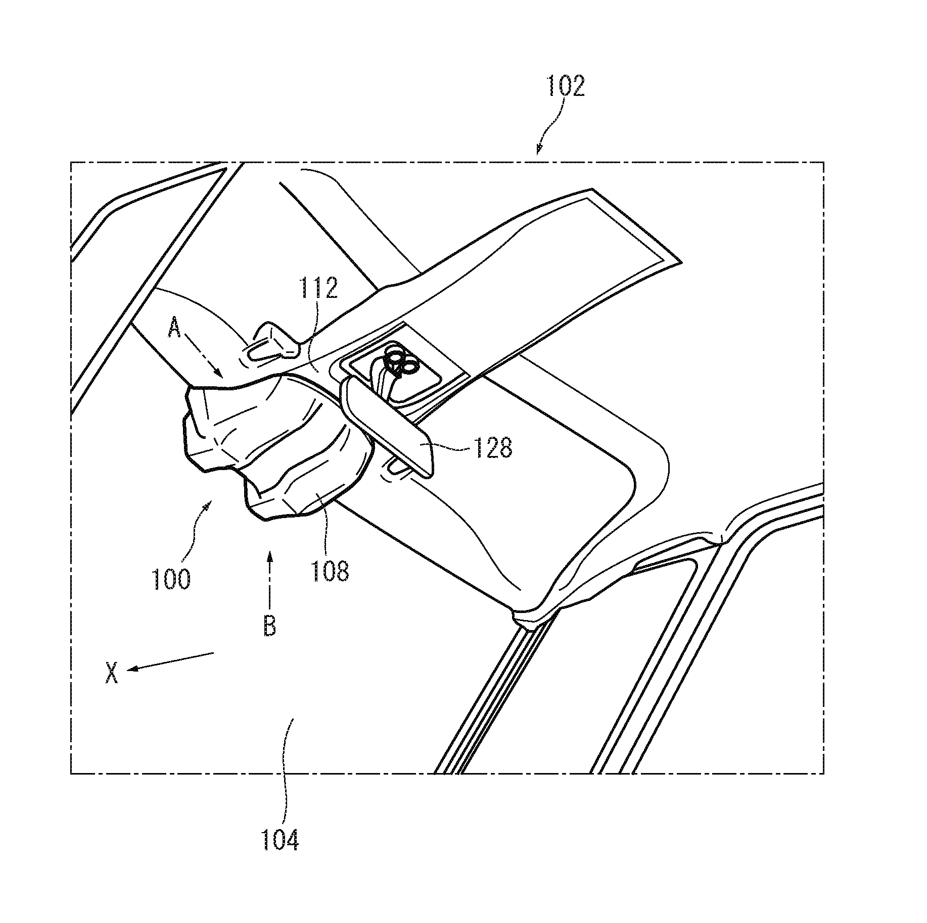
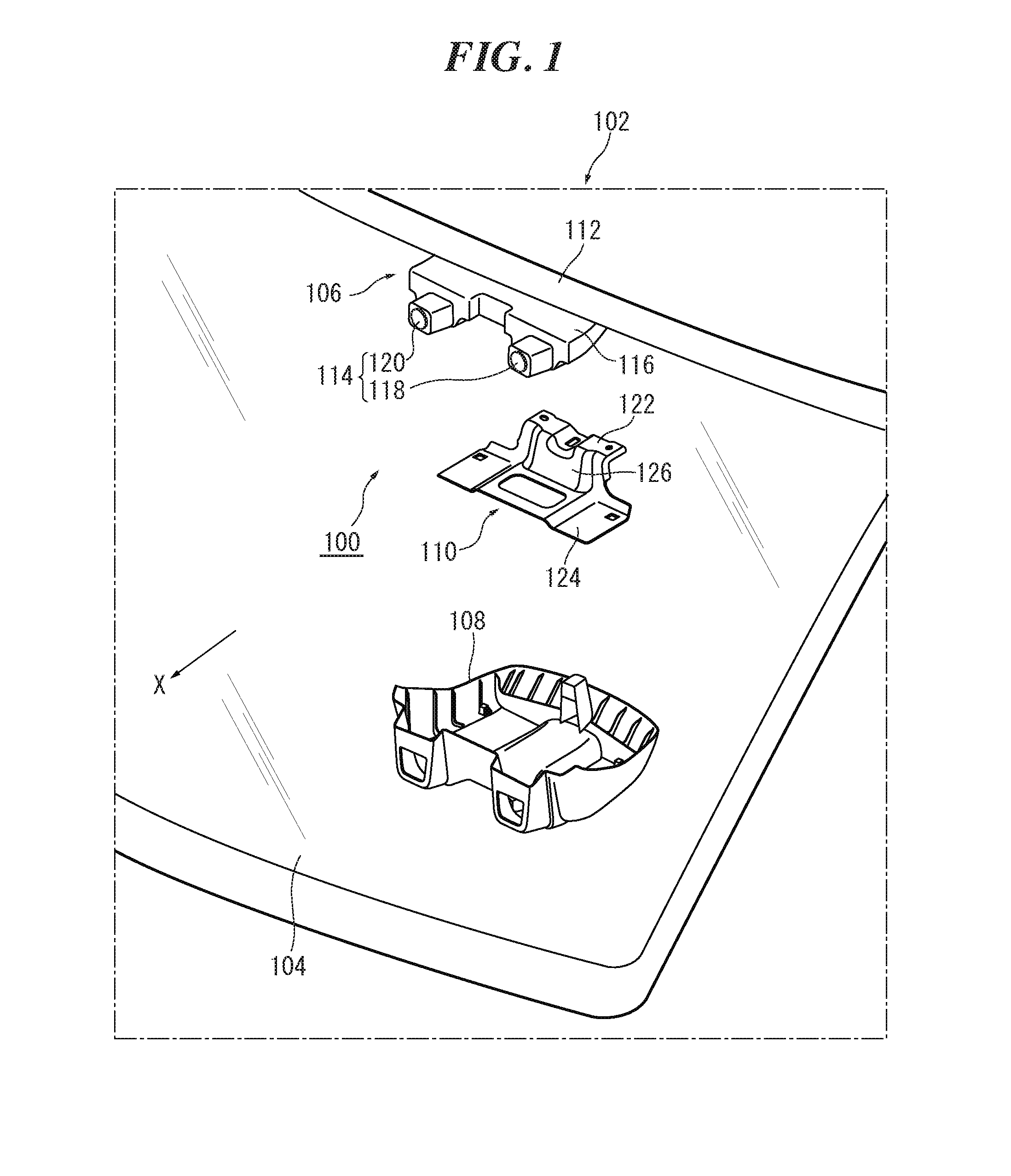
[0021]FIG. 1 is an exploded perspective view of an in-vehicle device covering structure 100 according to an embodiment of the invention. FIG. 1 shows the in-vehicle device covering structure 100 when viewed from a vehicle exterior side through a windshield glas...


PUM


Abstract

An in-vehicle device covering structure comprises an in-vehicle device attached to a ceiling surface of a vehicle, a cover that covers the in-vehicle device from below, and a plate-shaped bracket attached to the ceiling surface and covered by the cover from below together with the in-vehicle device, the cover hanging from the bracket. The bracket has a first attachment surface attached to the ceiling surface on the vehicle rear side relative to the in-vehicle device, a second attachment surface attached to the cover and arranged overlapping at least a chassis of the in-vehicle device when viewed in a vehicle upper-lower direction and at a distance from the in-vehicle device, and a vertical wall connecting the first and second attachment surfaces, the vertical wall being arranged on the vehicle rear side relative to the in-vehicle device and at a distance from the in-vehicle device.

Description


Claims


Application Information

Patent Timeline
IPC IPC(8): B60R11/04
CPCB60R2011/0028B60R11/04B60R13/02B60R2001/1253
Inventor YASUHARA, RYOTARO
Owner SUZUKI MOTOR CO LTD
Why Eureka
Try Eureka