Actively stabilized payload support apparatus and methods

a payload support and active stabilizer technology, applied in the direction of instruments, stands/trestles, camera body details, etc., can solve the problems of not being able to provide consistent stabilization control, most passive stabilizers require significant training time and effort to become technically proficient in their use,

Active Publication Date: 2016-11-17
WAGNER STEVEN D +3
View PDF0 Cites 14 Cited by
  • Summary
  • Abstract
  • Description
  • Claims
  • Application Information

AI Technical Summary

Benefits of technology

This invention relates to a way to keep things stable while they move. It uses two different types of movement: tilting (which affects how much something slopes) and rolling (which affects how smoothly it moves). A special sensor can measure this movement, and software programs use those measurements along with other data to calculate what kind of force should be applied to make everything balanced and steady. This technology results in smoother movements and better stability control.

Problems solved by technology

The technical problem addressed by this patent is how to provide stable footage when capturing images on small mobile equipment like cameras without requiring excessive training or skimming through trial and error. There is currently no reliable solution for effectively controlling the movement of these types of cameras during recording.

Method used


Image

  • Actively stabilized payload support apparatus and methods
  • Actively stabilized payload support apparatus and methods
  • Actively stabilized payload support apparatus and methods

Examples


Embodiment Construction

[0055]For simplicity, illustrative embodiments of the actively stabilized payload support will be described as they relate to a camera payload.

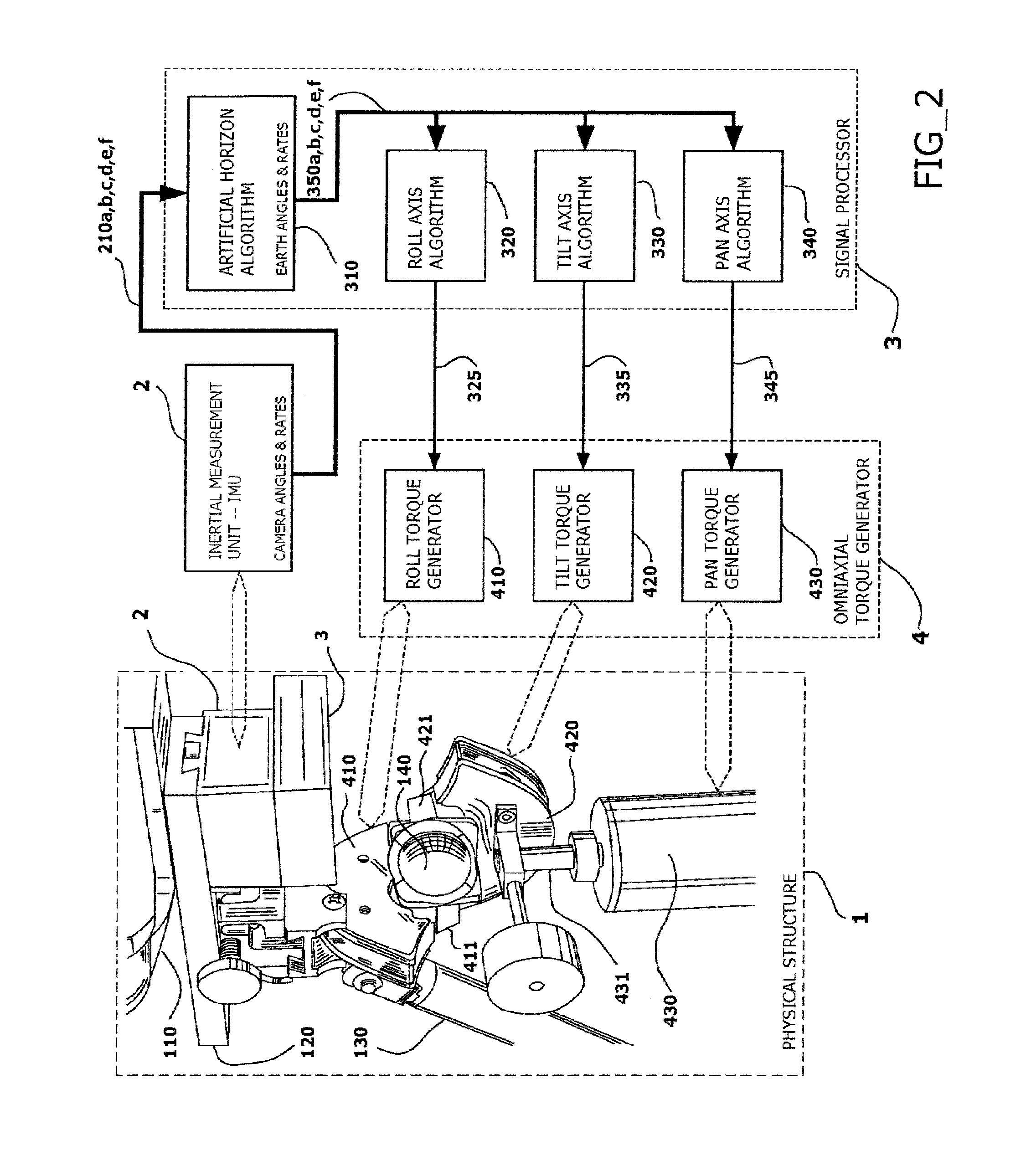
[0056]Illustrative embodiments of the actively stabilized payload support include an arrangement of interdependent sub-assemblies coupled in an interconnected continuous feedback loop fashion. In an illustrative embodiment, four possible sub-assemblies include:

1: Balanced Component Assembly

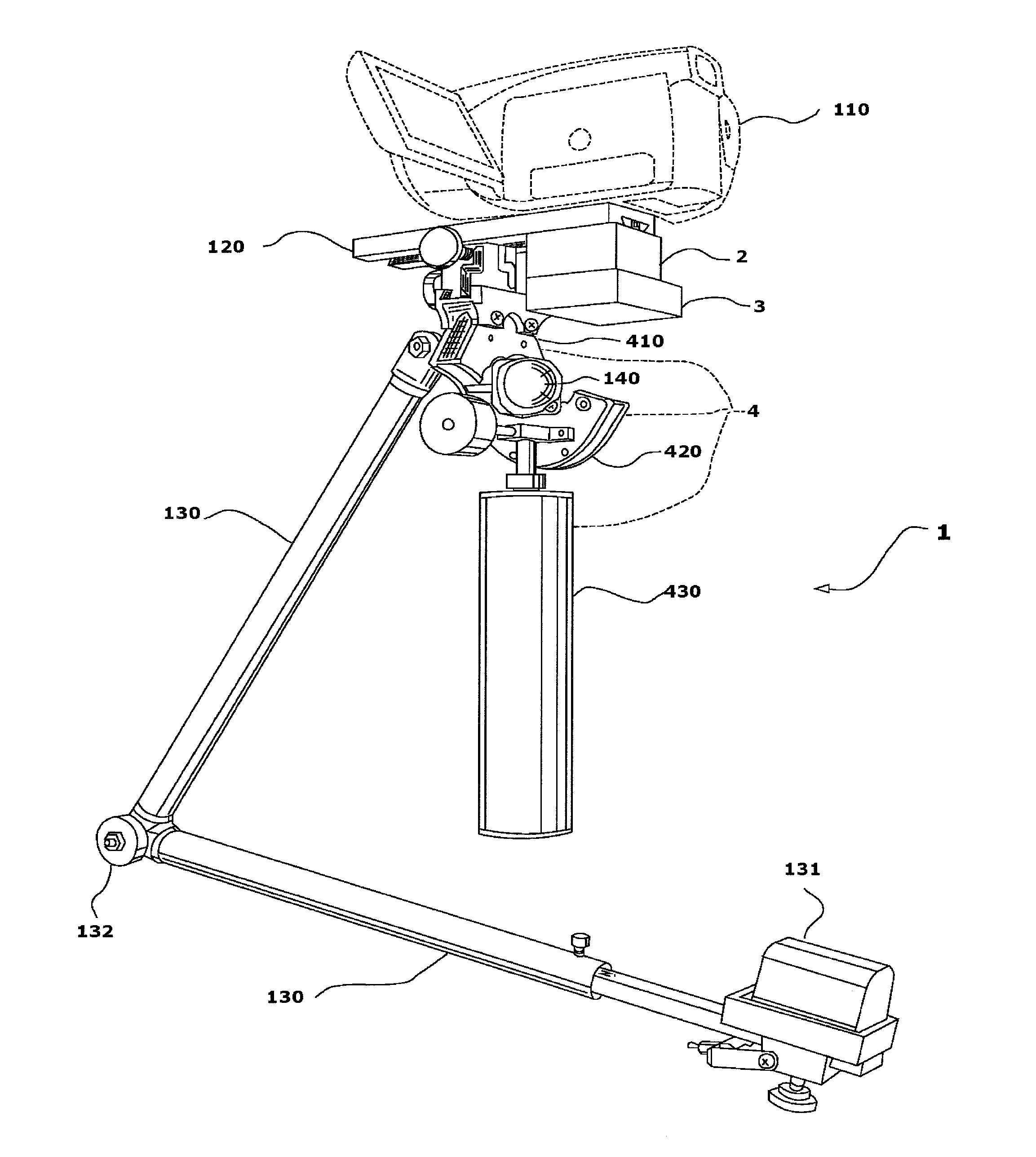
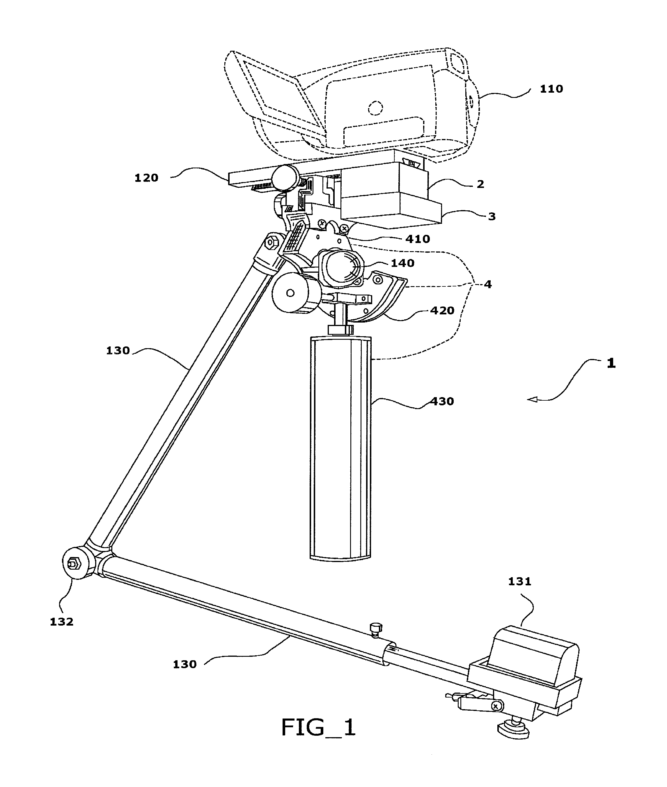
[0057]The balanced component assembly includes a “SLED” structure. An illustrative sled structure is described in U.S. Pat. No. 4,017,168, incorporated herein by reference, where it is designated as “equipment for use in hand held photography”. The sled structure will be referred to herein in an abbreviated manner as a rig or stabilizer. The stabilizer together with a payload, such as a camera and related equipment, will be referred to as a “balanced component assembly.”

[0058]FIG. 1 depicts a balanced component assembly according to an illustrative embodime...


PUM


Abstract

A payload stabilizer suitable for use with video camera payloads. The stabilizer has a feedback system providing supplemental torques to the payload through a gimbal while remaining responsive to direct operator control.

Description


Claims


Application Information

Patent Timeline
Owner WAGNER STEVEN D
Why Eureka
Try Eureka