Passive and active stability systems for ballistically launched multirotors

a multi-rotor and stability system technology, applied in the field of small unmanned vehicles (uavs), can solve the problems of inability to conventionally launch aircraft to gather this information, the blades of the multi-rotor are a hazard to nearby personnel, and the takeoff is one of the most dangerous parts of the flight of the multi-rotor, so as to facilitate handoff control and easy to see the ground

Pending Publication Date: 2021-04-15
CALIFORNIA INST OF TECH
View PDF8 Cites 10 Cited by
  • Summary
  • Abstract
  • Description
  • Claims
  • Application Information

AI Technical Summary

Benefits of technology

[0149]Further use cases include use in applications ranging from farmland and structural inspection to consumer platforms for personal video. The SQUID concept allows these multirotor platforms to be either dropped to a location from another aerial vehicle, launched to a high altitude, or cover a long distance without expending the on-board battery power. In agriculture, SQUID multirotors could be automatically launched to altitude, hover to take photos, and then descend under battery power, providing an efficient means of obtaining crop and irrigation status while only draining battery power for the hover and descent. For security, a SQUID multirotor could also be used to investigate intrusions on perimeter of a fixed protected area, rapidly covering the distance from a centralized depot through an automated launch. For consumer products, given the popularity of both drones and model rockets among aerospace hobbyists, SQUID may also be sold to consumers for a variety of purposes. For environmental monitoring, SQUID allows a sensor payload to be launched and returned from places difficult for standard multirotors to fly, such as to high altitudes, into strong headwinds, or rapidly through conditions that would be untenab

Problems solved by technology

Aerial systems that can instead be launched ballistically without operator intervention will play an important role in emergency response, defense, and space exploration where situational awareness is often required, but the ability to conventionally launch aircraft to gather this information is not available.
Likewise, military personal in active engagements could quickly deploy aerial assets to gather information as the situation evolves and may not have time to manually launch information gathering drones.
The rotating blades of the multirotor are a hazard to nearby personnel (who may be distracted by other obligations), a problem which is particularly present if the system is to launch autonomously without human supervision.
In addition, takeoff is one of the most dangerous portions of a multirotor's flight, as it involves hazards to not only the multirotor but also other assets on the ground.
Current drone designs are slow to deploy, require user intervention prior to takeoff, and cannot be deployed from a moving vehicle.
Furthermore, traditional foldable designs require the user to unfold the arms, slowing the process and putting the user at risk.
The current dep

Method used


Image

  • Passive and active stability systems for ballistically launched multirotors
  • Passive and active stability systems for ballistically launched multirotors
  • Passive and active stability systems for ballistically launched multirotors

Examples


embodiment one (

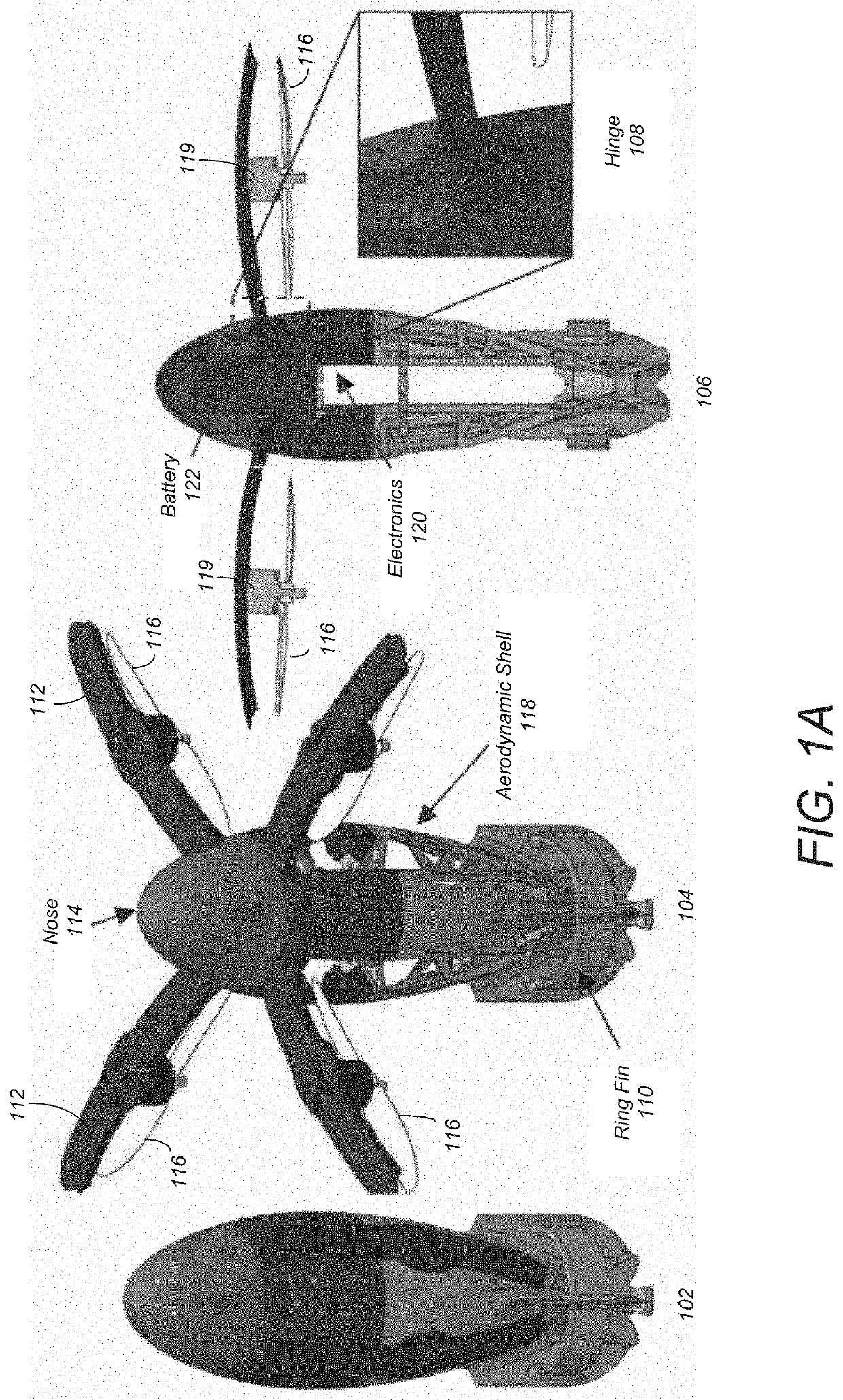
Vehicle Embodiment One (1)

[0040]Design

[0041]Requirements for the first design option may include: (a) it will be launched from an approximately 3 inch tube (70-85 mm) (although different size tubes and / or no tube may be utilized); (b) it should fly ballistically to reach an altitude of 10 m; (c) it should be able stabilize its flight after launch. In addition, (d) it should be a multirotor, and (e) it should be able to carry a payload of 200 g.

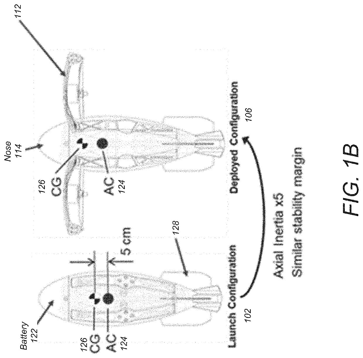
[0042]From this set of requirements, one can derive functional requirements that help the design process: the first requirement sets a form factor and, combined with requirement (d), requires that the vehicle be able to deploy its arms that hold the rotors. Requirement (a) also implies high vertical loads during launch, which will drive the structural design. Requirement (e) does not constrain the design space, as the vehicle is more volume limited than thrust limited.

[0043]This design focuses on the new challenges compared to a standard multi...

embodiment two (

Vehicle Embodiment Two (2)

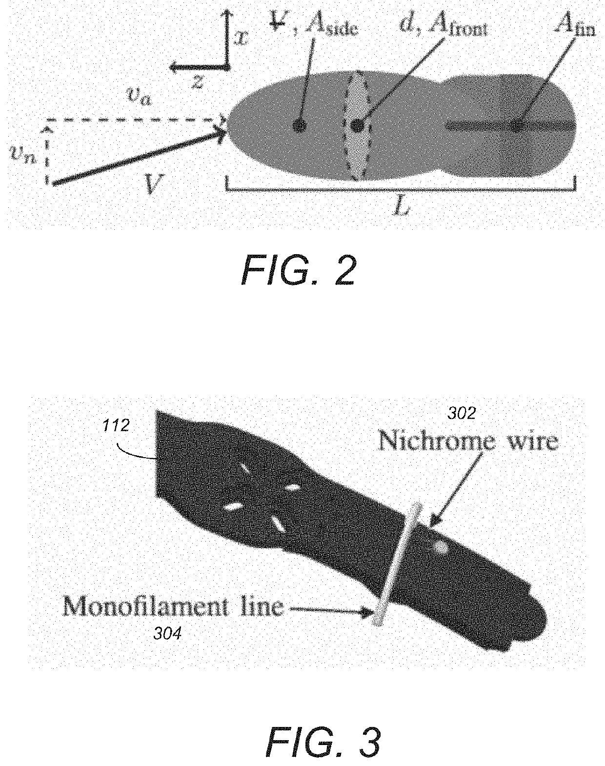
[0083]Embodiment 1 above describes a small prototype, a folding quadrotor that launches from a 3-inch tube to a height of 10 m or more, and then passively unfolds to a fully functional multirotor when triggered by a nichrome burn wire release mechanism. Such embodiments introduce the basic aerodynamic principles and structural design concepts required to sustain the g-forces associated with a ballistic launch. A prototype was fabricated and ballistically launched from a vehicle moving at speeds of 80 km / h (22 m / s). However, the multirotor was stabilized by a remote pilot after the ballistic launch phase.

[0084]Embodiment 2 provides a larger prototype that can launch from a 6 inch-diameter tube, propelled by expanding CO2. Embodiment 2 also demonstrates autonomous self-stabilization after the ballistic phase. Moreover, embodiment 2 demonstrates that the vehicle can carry a significant sensor payload (illustrating that ballistically launched multirotors can ca...


PUM


Abstract

A ballistically launched foldable multirotor vehicle has a central body frame. A battery is located in an upper vertical location of the vehicle and positions a center of mass of the vehicle to provide aerodynamic stability during a launch. Fins are attached to the central body frame such that aerodynamic forces on the fins shift an aerodynamic center (AC) of the vehicle downward below the center of mass of the vehicle. Three or more foldable arms are attached to the central body frame via a hinge and exist in two states—a closed state where the foldable arms are parallel to a central body axis, and an open state (after launch) where the foldable arms extend radially outward perpendicular to the central body axis. Rotors mounted to each foldable arm are controlled by a motor to enable flight.

Description

CROSS-REFERENCE TO RELATED APPLICATIONS[0001]This application claims the benefit under 35 U.S.C. Section 119(e) of the following co-pending and commonly-assigned U.S. provisional patent application(s), which is / are incorporated by reference herein:[0002]Provisional Application Serial No. 62 / 912,989, filed on Oct. 9, 2019, with inventor(s) Jacob Izraelevitz and Brett A. Kennedy, entitled “Squid (Streamlined Quick-Unfolding Investigator Drone): A Projectile-Launched Multirotor Vehicle Platform,” attorneys' docket number 176.0169USP1 / CIT7905P; and[0003]Provisional Application Ser. No. 63 / 037,159, filed on Jun. 10, 2020, with inventor(s) Brett A. Kennedy, Jacob Izraelevitz, Amanda Bouman, Daniel Pastor Moreno, Matthew J. Anderson, Paul M. Nadan, and Joel W. Burdick, entitled “Squid (Streamlined Quick-Unfolding Investigator Drone) Passive Stability System,” attorneys' docket number 176.0169USP2 / CIT8484P.STATEMENT REGARDING FEDERALLY SPONSORED RESEARCH AND DEVELOPMENT[0004]This invention ...

Claims


Application Information

Patent Timeline
IPC IPC(8): B64C39/02B64D27/24B64C5/06B64C1/30B64C27/32B64C1/06B64C25/32B64F1/04B64D47/08
CPCB64C39/024B64D27/24B64C5/06B64C1/30B64C27/32B64C1/061F41F3/052B64C25/32B64F1/04B64D47/08B64C2201/042B64C2201/108B64C2201/141B64C1/0683F42B10/50F42B15/08B64U70/00B64U10/13B64U50/19B64U30/20B64U2101/00B64U30/12
Inventor IZRAELEVITZ, JACOB S.KENNEDY, BRETT A.BOUMAN, AMANDA R.PASTOR MORENO, DANIELANDERSON, MATTHEW JAMES LINDSAYNADAN, PAUL M.BURDICK, JOEL W.
Owner CALIFORNIA INST OF TECH
Why Eureka
Try Eureka