Mobile drip irrigation with precise and uniform water distribution

a technology mobile drip irrigation, which is applied in the field of precise and uniform water distribution of mobile drip irrigation, can solve the problems of significant water loss due to evaporation before the remaining water, sprayed water which reaches the plants is susceptible to some evaporation, and the amount of water lost by evaporation is still significant, so as to facilitate the movement of the drip tube, facilitate the reversal of the direction of the mobile drip irrigation system, and facilitate th

Active Publication Date: 2016-08-23
TEETER MONTY J
View PDF26 Cites 3 Cited by
  • Summary
  • Abstract
  • Description
  • Claims
  • Application Information

AI Technical Summary

Benefits of technology

[0012]This invention involves anchoring and retaining drip tubes of a mobile drip irrigation device at substantially fixed positions and intervals relative to a water distribution conduit of the mobile drip irrigation device to guide the drip tubes through an agricultural field and to facilitate keeping the drip tubes moving in desired pathways or tracks. The substantially fixed positions and intervals establish the pathways of the drip tubes to distribute the water in a uniform and precisely controlled pattern throughout the agricultural field, thereby ensuring that the growing plants receive the optimal amount of water to grow and achieve enhanced productivity without wasting or ineffectually applying the water. Water emitters of the drip tubes deliver a predetermined constant flow or volume of water to enable each drip tube to deliver a precisely controlled amount of water onto the soil over the pathway traversed.
[0013]The invention also involves solving many of the operational deficiencies of previous mobile drip irrigation systems. Anchoring and retaining the drip tubes at substantially fixed positions and intervals inhibits the drip tubes from tangling with one another, with the wheels of the motorized towers, with the growing plants, and with the furrows in which the plants are growing. Reversing the direction of the mobile drip irrigation system is facilitated by providing a capability for flexibility, bending and pivoting at the leading ends of the drip tubes. The flexibility, bending and pivoting capability allows the drip tubes to reverse direction without kinking or choking off the water supply. The leading end of the drip tubes also have an enhanced resistance to abrasion caused by movement over the ground, thereby reducing the occurrence of holes worn into the drip tubing. Overcoming these previous operational deficiencies allows the mobile drip irrigation device to operate in a reliable, consistent and constant manner while incurring less downtime, thereby achieving more effective irrigation.
[0019]Subsidiary and other aspects of the invention involve some or all of the following features. The forward ends of the drip tubes are anchored and retained against substantial movement perpendicularly and longitudinally relative to the water distribution conduit. The predetermined positions of the forward ends of the drip tubes are within distance of about four feet above the soil. A plurality of substantially rigid drop tubes are connected to receive water from the water distribution conduit at an upper portion of the drop tube, and the lower portion of each drop tube is connected to the forward end of one drip tube, with the lower portion of each drop tube anchored and retained to establish the predetermined positions from which the connected drip tube is guided over the soil and through plants. The upper portion of the rigid drop tube is also anchored and retained to assist in establishing the predetermined positions for guiding the drip tubes. Anchoring and retaining the substantially rigid drop tubes at their upper portions is accomplished by an anchoring cable extending between adjacent motorized towers which support the water distribution conduit above the soil and by a guide member connected to a lower portion of each drop tube. A manifold is connected to receive water from the water distribution conduit and supply the water to drip tubes connected to the manifold. The manifold is anchored and retained to establish the predetermined positions from which the connected drip tubes are guided over the soil and through plants. Each drip tube comprises a section of wear resistant relatively flexible hose and a section of relatively less flexible water emitting tubing connected to the flexible hose section for delivering water onto the soil. The flexible hose section has sufficient length to curve downwardly into contact with the soil and orient the water emitting section essentially parallel to the soil. The flexible hose section, or a coupling with relatively rotational inlet and outlet portions, guides the drip tube through a reversal in direction of movement without kinking or inducing a permanent bend in the drip tube.

Problems solved by technology

A significant portion of the emitted water is nebulized when the jet is created, resulting in a significant loss of water due to evaporation before the remaining water reaches the soil.
However the amount of water lost to evaporation is still significant, and even the sprayed water which reaches the plants is susceptible to some evaporation due in part to some of the water collecting on the leaves and evaporating before reaching the soil.
Even though mobile drip irrigation systems are recognized as offering a greater potential for water conservation, previous mobile drip irrigation systems have not been widely accepted, despite their availability for many decades.
The lack of acceptance is centered around uneven and unreliable water distribution coupled with many practical and operational problems associated with using previous mobile drip irrigation systems.
One problem of previous mobile drip irrigation systems is an inability to reliably and consistently control the paths taken by the drip tubes as they are pulled through the agricultural field.
When the pathways of adjacent drip tubes diverge, gaps and spaces occur in the field where little or no water is distributed.
Of course, those gaps with inadequate or no water do not promote the growth of the agricultural plants, but instead encourage the growth of naturally occurring weeds which diminish the overall quality of the agricultural production.
Those plants which grow despite minimal irrigation are diminished in size and their maturity is delayed, which again diminishes the overall productivity from the agricultural field.
One operational problem which has plagued previous mobile drip irrigation systems is that the drip tubes frequently become tangled together due to the lack of control over the pathways taken by the drip tubes.
Agricultural plants which have stiff stalks have the capability of tangling the drip tubes, thereby misdirecting the drip tubes from their intended movement pathways.
Reversing direction in previous mobile drip irrigation systems is particularly problematic because the reversal kinks or bends the drip tubes enough to choke off or substantially diminish water emission, even after the reversal in direction is completed.
The drip tubes of previous mobile drip irrigation systems are also susceptible to accelerated wear due to the friction of moving over the soil, particularly during cold weather and when used in sandy soil or soil which contains a large content of substantially sized solid particles.
The frozen, sandy or particulate soil creates enough friction against the drip tubes as they move over the soil to wear unintended openings in the drip tube through which excess and uncontrolled water is delivered.
While taking the necessary corrective action, the mobile drip irrigation system is inoperative.
Because of the persistent and repeating nature of these problems, the time required to undertake the corrective actions may reduce the amount of irrigation of the agricultural field as a whole to the point where the productivity of the agricultural crop is compromised.

Method used


Image

  • Mobile drip irrigation with precise and uniform water distribution
  • Mobile drip irrigation with precise and uniform water distribution
  • Mobile drip irrigation with precise and uniform water distribution

Examples


Embodiment Construction

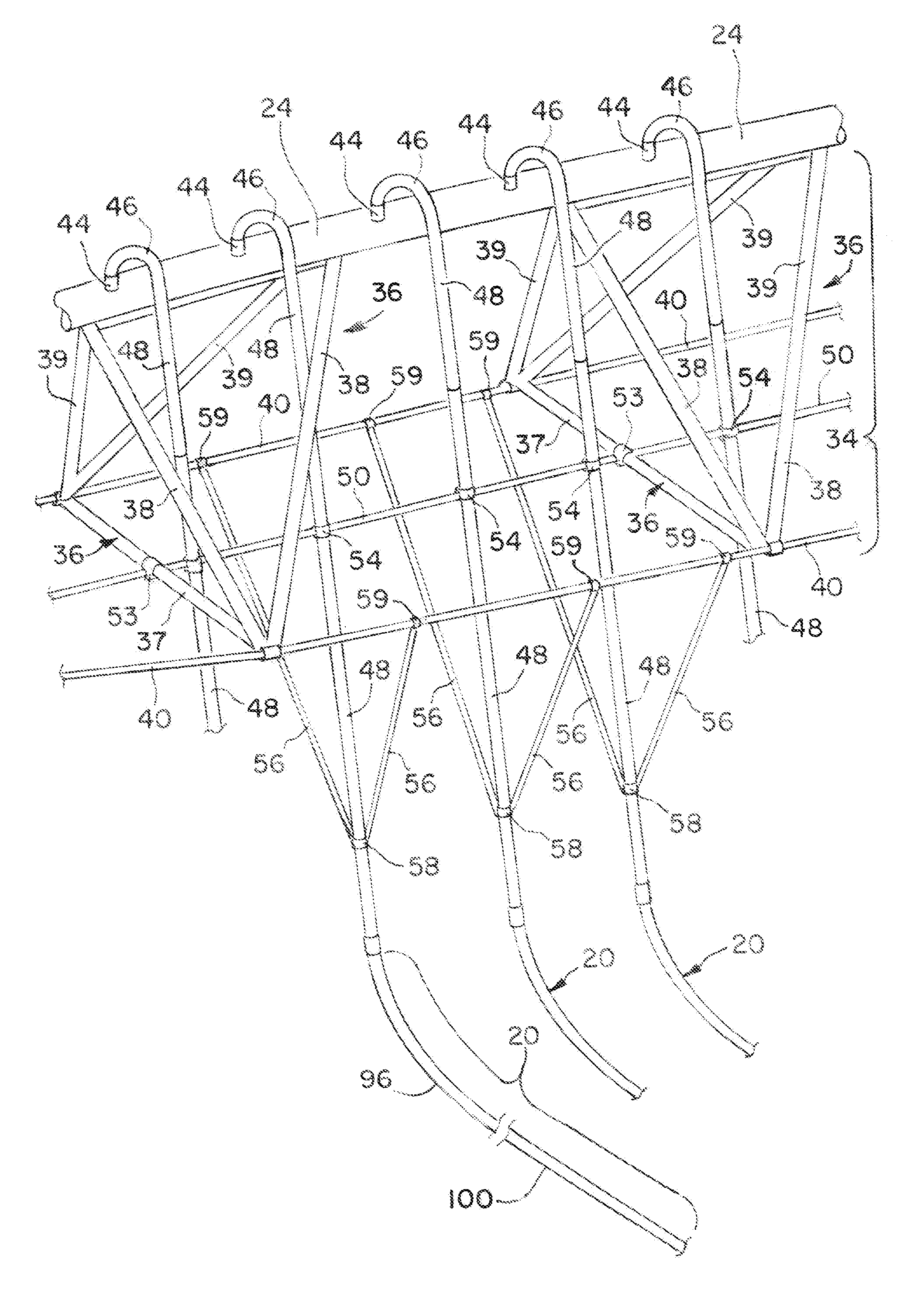
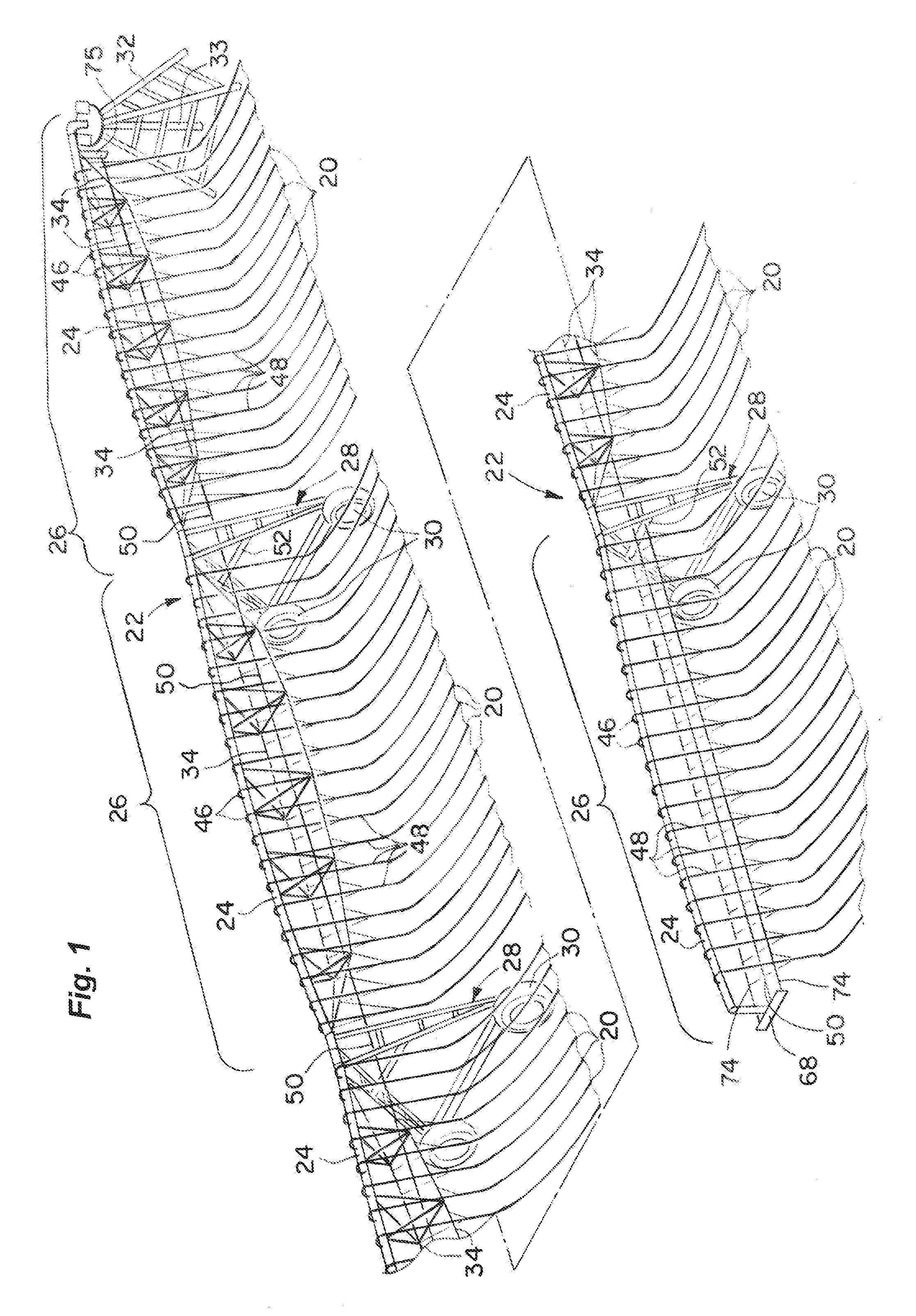
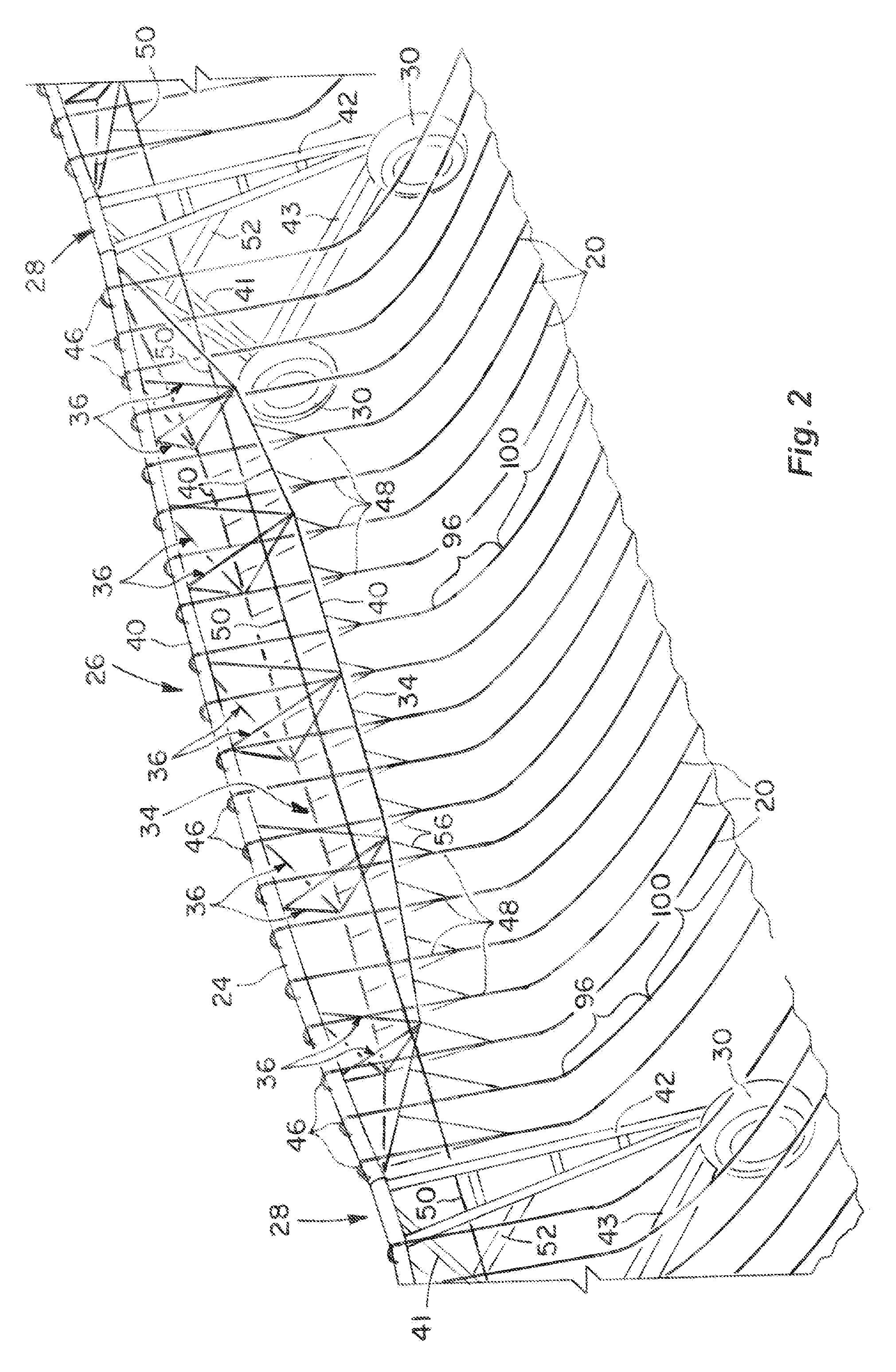
[0030]The present invention involves anchoring, retaining, positioning and using drip tubes 20 in a mobile drip irrigation device 22, shown in FIGS. 1 and 2. When the drip tubes 20 are anchored, retained, positioned and used in the manner discussed in more detail below, irrigation water is more precisely, uniformly and effectively distributed over an agricultural field where plants are growing in soil, while simultaneously achieving significant operational and functional improvements.

[0031]The mobile drip irrigation device 22 comprises an overhead water distribution conduit 24 formed as a number of connected segments 26 of the device 22. Each device segment 26 extends between and is supported by a motorized tower 28. Each tower 28 includes two wheels 30 which engage the soil of the agricultural field and which are driven by electric or hydrostatic motors (not shown). The wheels 30 of each tower 28 move the distribution conduit 24 over the agricultural field.

[0032]An inner end of the...


PUM


Abstract

Water is emitted directly onto the soil from drip lines pulled from a mobile drip irrigation device. The forward ends of the drip tubes are anchored and retained to establish relatively fixed intervals of spacing between the forward ends of the adjacent drip tubes to guide the drip tubes across the soil and through growing plants. A pressure-regulated constant-volume flow of water is emitted from ports in the drip tubes.

Description

[0001]This invention relates to mobile drip irrigation in which drip tubes are pulled across the soil to directly emit water onto the soil for irrigating growing plants. More particularly, the present invention relates to new and improved techniques for more precisely and effectively distributing the water from the drip tubes over an entire agricultural field, resulting in enhanced and earlier growth of the plants, less water use and more effective irrigation from the available water used. Further still, the present invention involves overcoming significant practical and operational problems of previous mobile drip irrigation systems to achieve more reliable and trouble-free operation.BACKGROUND OF THE INVENTION[0002]The typical mobile irrigation systems uses an overhead water distribution conduit which is supported by motorized towers that move the water distribution conduit over an agricultural field. Predominantly, such mobile irrigation systems are a center pivot type, in which ...

Claims


Application Information

Patent Timeline
Patent Type & Authority Patents(United States)
IPC IPC(8): A01G25/09
CPCA01G25/09Y02A40/22A01G25/023A01G25/092
Inventor TEETER, MONTY J.
Owner TEETER MONTY J
Why Eureka
Try Eureka