Surgical device for correction of spinal deformities

a spinal column and surgical technology, applied in the direction of osteosynthesis devices, internal osteosynthesis, internal osteosynthesis, etc., can solve the problem of minor amount of this common rotational movement, and achieve the effect of gradual correction of spinal column deformation, and increased distance or separation between the two limbs

Active Publication Date: 2016-11-24
CONCEPT SPINE
View PDF1 Cites 3 Cited by
  • Summary
  • Abstract
  • Description
  • Claims
  • Application Information

AI Technical Summary

Benefits of technology

[0032]In one embodiment, the stem includes a longitudinal split along its longitudinal axis. The split may extend along the entire length or along only part of its length. The split may be arranged preferably, but not exclusively, along the sagittal plane (when installed in use). It may at least partially separate the stem into two limbs. In use the distance or separation between the two limbs may be increased temporarily and reversibly. This separation may allow the ratchet(s) to be temporarily overcome such that the angle between the stem and the bone fixing element may be set during installation. After this step the separation of the two limbs may be reduced such the influence of the ratchet(s) is again enforced over this angle.
[0033]In a second aspect, the invention provides a surgical device for correction of deformities of the spinal column comprising at least two mutually interconnectable segments arranged for affixation on at least two separate vertebrae of the spinal column, each segment comprising a first part, equipped with at least one bone fixing element adapted for affixation on at least one vertebra of the spinal column, a second part, connectable to the said first part at an axially arranged connection permitting rotation of the said first and second parts relative to each other around a first axis, the said second part also being equipped with at least one stem able to withstand mechanical loads during use, the said second part also being equipped with at least one connecting hole of design appropriate, firstly, to allow insertion of the said stem of at least one other segment of the surgical device disclosed herein to the said connecting hole and, secondly, to allow pivoting (angular movement) and axial sliding of the said stem in the said connecting hole, a ratchet arrangement of the said axially arranged connection between the said first and second parts permitting, in use, the said first and second parts to rotate relative to each other around the said first axis of rotation in a single predetermined direction but preventing the said first and second parts from rotating around the said first axis of rotation in an opposite direction, wherein, during use, at least two mutually interconnected segments of the surgical device disclosed herein are affixed on at least two separate vertebrae of the spinal column, the said stem of the said second part of the segment affixed on the vertebra above being axially inserted in the said connecting hole of the said second part of the segment affixed on the vertebra below, permitting angular movements between the said two vertebrae of the spinal column in the desired direction of correction of the deformity but preventing any angular movement between the said two vertebrae of the spinal column in the opposite to the said desired direction, and wherein, during normal daily activity or special exercise-induced movements of the human spinal column, any loads applied to the spinal column directed in a direction opposite to the said desired direction of correction of the said spinal deformity are endured, resisted and prevented by at least two mutually interconnected segments of the surgical device disclosed herein, whilst all other loads are endured solely by the spinal column protecting thus the surgical device disclosed herein from mechanical failure or loosening of its secure affixation on a vertebrae of the spinal column, and whereby, over a period of time, gradual correction of the said spinal deformity can be achieved without additional force generating means.
[0034]As described herein there is provided a surgical device for gradual correction of deformities of the spinal column without fusion of the involved part of the spinal column. The device may comprise mutually interconnected segments affixable to separate vertebrae of the spinal column. Their arrangement may comprise a ratchet as part of a pivoting connection between the part affixed to the bone and a support. The support may have a connecting opening to permit free relative rotation and axial movement, but which may restrict relative angulatory movement at least in one plane, between the mutually interconnected segments.
[0035]The configuration of the surgical device may permit gradual angular correction of the relative position of the vertebrae while at the same time all other movements, including those affected by axial loading of the spinal column are allowed. It is to be appreciated that gradual correction of a deformity of the spinal column may be achieved over a period of time following the application of the surgical device effected by active and passive movements of the spinal column during normal daily activities and exercising while, at the same time, the mobility of all parts of the spinal column may be preserved.

Problems solved by technology

However, the amount of this common rotational movement may be minor compared to the opposite rotational movement effected due to the individual's typical daily activities.

Method used


Image

  • Surgical device for correction of spinal deformities
  • Surgical device for correction of spinal deformities
  • Surgical device for correction of spinal deformities

Examples


third embodiment

[0078]the device 210 is shown in FIG. 4. It comprises a stem 212 attached to one side 214 of a rotational ratchet 220, and a bone fixing element 230 comprising a screw thread 234 and a shaft 232 directly attached to the other side 218 of the ratchet 220. The two sides 214, 218 make up the rotation means 211 (which is substantially cylindrical in shape). The ratchet 220 restricts relative rotational movement of the two sides in a similar manner to that described above.

[0079]In this embodiment, a socket 238 is provided in the body of the rotation means 211. This socket may receive a stem 212 from an adjacent device 210, in a similar manner to that described above, such that an array of devices 210 may be interconnected. The socket 238 is arranged such that the stem 212 may rotate and move axially and angularly within it thus allowing a certain amount of freedom of movement between adjacent vertebrae other than that restricted by the ratchet 20.

fourth embodiment

[0080]the device 310 is shown in FIG. 5. This device 310 is similar to the device 210 shown in FIG. 4 except that the shaft 332 of the bone fixing element 330 is not directly attached to the rotation means 311, which is substantially cylindrical in shape. Rather, a socket 316 is provided in the body of the rotation means 311 adjacent the socket 338 for receiving the stem 312 of an adjacent device 310. This socket 316 may receive the shaft 332 of the bone fixing element 330. The socket 316 is arranged such that the stem 312 may rotate and move axially and angularly within it thus mallowing a certain amount of freedom of movement between adjacent vertebrae other than that restricted by the ratchet 20. This is more clearly shown in FIG. 6.

[0081]The axial movement is referenced “F”, the rotational movement is referenced “E”, and the angular movement is referenced “G”. All other features are the same as described with regard to FIG. 5.

[0082]FIG. 7 shows two devices 310 arranged together,...

ninth embodiment

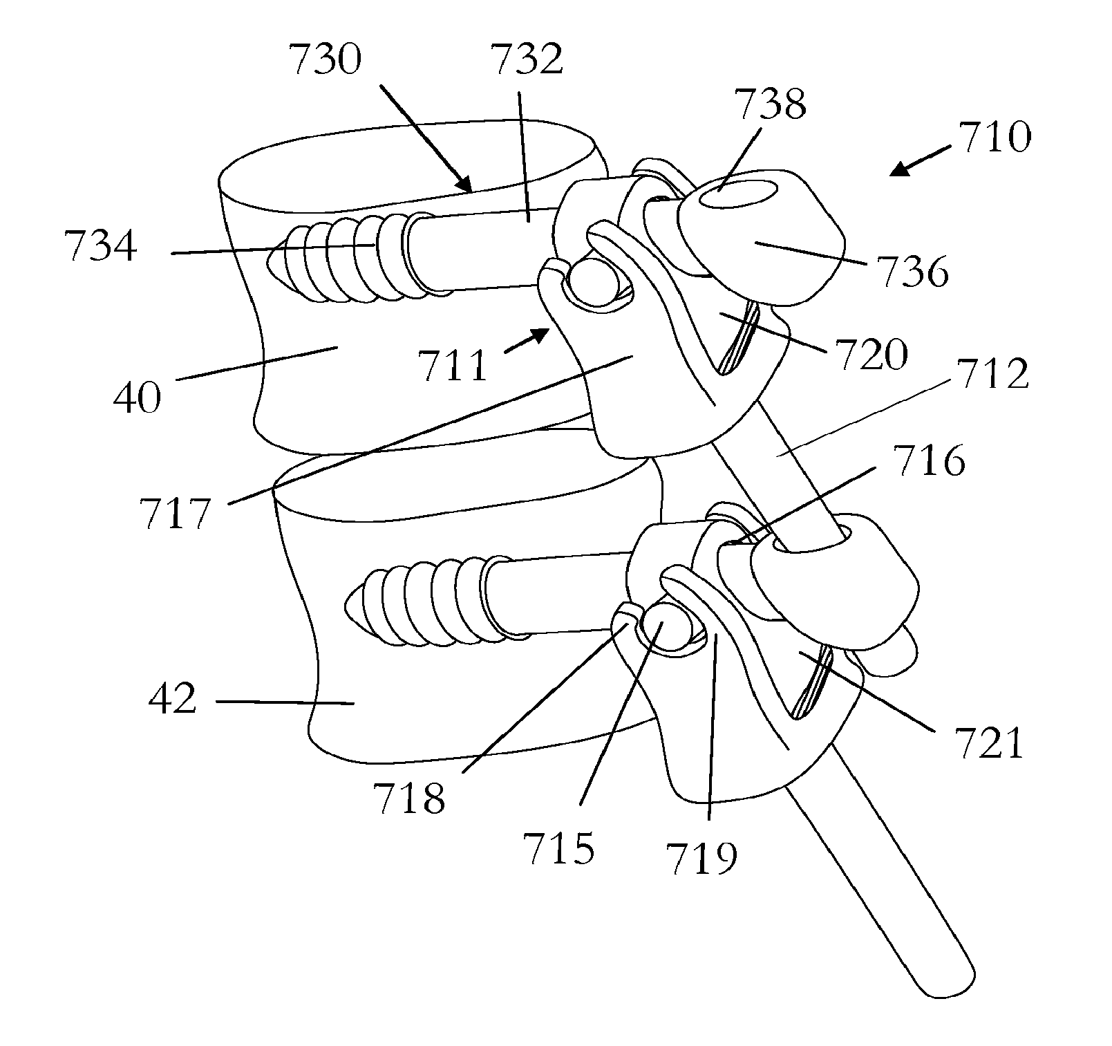
[0089]A ninth embodiment is shown in FIG. 15. This embodiment 710 comprises a bone fixing element 730 which comprises a thread 734, a shaft 732 and a head 736. The head includes a socket 736 for receiving the stem 712 of an adjacent device 710. The stem 712 is attached to, or integral with one half 717 of the rotation means 711. This rotation means permits relative rotation between the stem 712 and the bone fixing element 730 around an axis which substantially lies long the intersection of the transverse and coronal planes. The rotation means 711 comprises a body 717 at the base of which the stem 712 is connected and at the upper end of which two arms 718, 719 are provided. The other half of the rotation means 711 comprises a body 721 on which are provided two axles or pins 715 (only one being shown) around which the two arms 718, 719 are arranged thus allowing relative rotation of the two halves 717, 721.

[0090]The body 721 also includes a female socket 716 through which the shaft 7...


PUM


Abstract

The present invention relates generally to a surgical device for the correction of deformities of the spinal column and finds particular, although not exclusive, utility in devices which are surgically implantable. Presently known implantable surgical devices are unable to provide for the progressive correction of spinal deformities assisted by active movements of the human body without fusion of the involved part of the spinal column. The present surgical device comprises a spinal column straightening means for permitting the relative rotation of two substantially adjacent vertebrae about a common axis substantially only in opposite rotational directions.

Description

CROSS-REFERENCE TO RELATED APPLICATION[0001]The present non-provisional patent application is a continuation-in-part of application Ser. No. 13 / 133,405, filed Jun. 8, 2011, and entitled SURGICAL DEVICE FOR CORRECTION OF SPINAL DEFORMITIES, which is incorporated in full by reference herein. The present non-provisional patent application claims the benefit of priority of: foreign Patent Application No. GB0822507.0, which is entitled SURGICAL DEVICE FOR CORRECTION OF SPINAL DEFORMITIES and which was filed Dec. 10, 2008; foreign Patent Application No. GB0902416.7, which is entitled SURGICAL DEVICE FOR CORRECTION OF SPINAL DEFORMITIES and which was filed Feb. 16, 2009; foreign Patent Application No. GB0913457.8, which is entitled SURGICAL DEVICE FOR CORRECTION OF SPINAL DEFORMITIES and which was filed Aug. 3, 2009, all of which are incorporated in full by reference herein.FIELD OF THE INVENTION[0002]The present invention relates generally to a surgical device for the correction of deform...

Claims


Application Information

Patent Timeline
Patent Type & Authority Applications(United States)
IPC IPC(8): A61B17/70
CPCA61B17/7001A61B17/7046A61B17/7007
Inventor KARNEZIS, IOANNIS
Owner CONCEPT SPINE
Why Eureka
Try Eureka