Monitoring system and monitoring method

Active Publication Date: 2016-11-24
ORMON CORPORATION
View PDF6 Cites 13 Cited by
  • Summary
  • Abstract
  • Description
  • Claims
  • Application Information

AI Technical Summary

Benefits of technology

[0019]The present invention enables easy realization of monitoring of the status of a monitoring targ

Problems solved by technology

However, conventional monitoring systems presuppose installation of sensors in a monitoring target, and therefore they have to be designed specifically in accordance with

Method used


Image

  • Monitoring system and monitoring method
  • Monitoring system and monitoring method
  • Monitoring system and monitoring method

Examples


Example

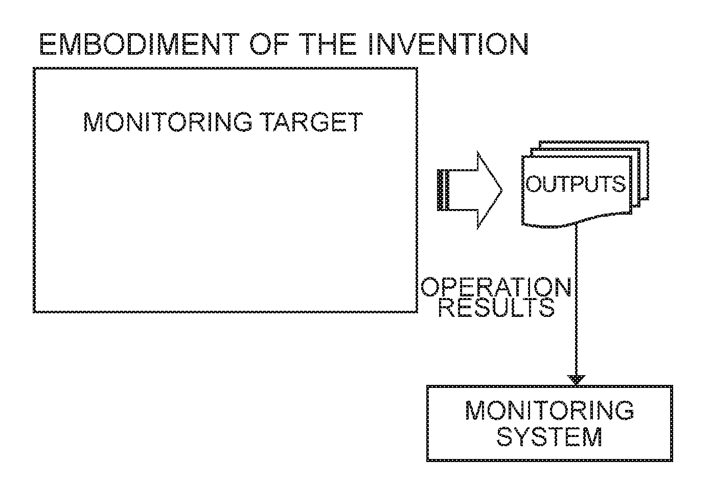
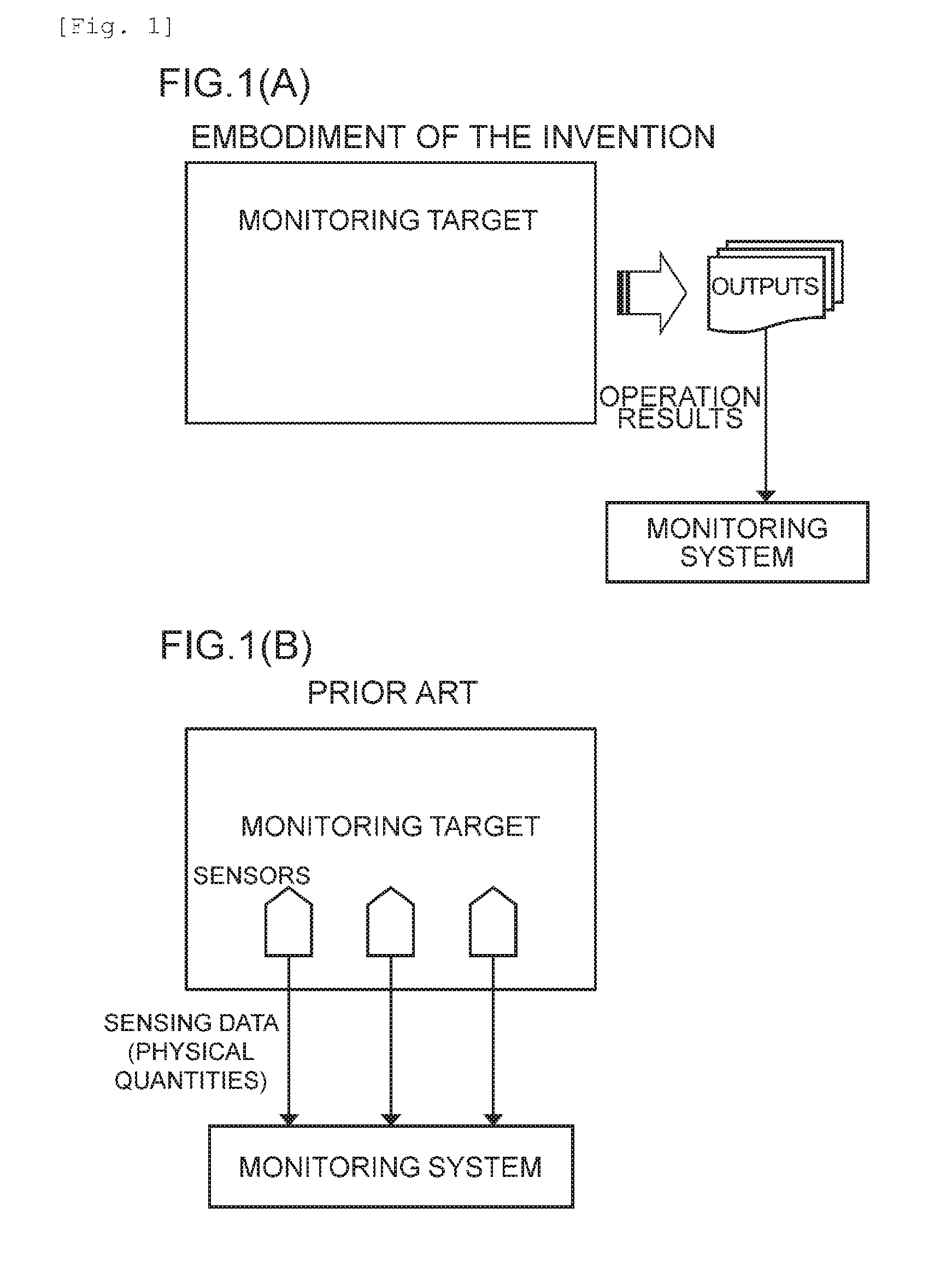
[0031]The monitoring system according to one embodiment of the present invention relates to a technique for constantly monitoring the status of a monitoring target, and detecting an abnormality or a predictor thereof or analyzing the cause of the abnormality. One characteristic feature of the monitoring system of this embodiment is that time series data of a plurality of indexes indicative of operation results of the monitoring target are utilized for the monitoring of the status and detection of an abnormality or a predictor thereof. FIG. 1 is a schematic diagram illustrating the difference in approach between a typical conventional monitoring system and the monitoring system of the embodiment of the invention in respect of this characteristic feature.

[0032]In the conventional monitoring system, as shown in FIG. 1(B), it is the common approach to set various sensors in the monitoring target to monitor physical quantities of actions in the monitoring target itself (sensing data). Th...


PUM


Abstract

Provided is a monitoring system including an operation results acquisition unit that acquires time series data of each of a plurality of indexes that indicate operation results of a monitoring target; an overall index generation unit that produces time series data of an overall index by combining a plurality of index values at a same time point based on the time series data of each of the plurality of indexes; and a change point detection unit that analyzes the time series data of the overall index, and detects a point where a significant change appears in the overall index values, as a change point in a status of the monitoring target.

Description

TECHNICAL FIELD[0001]The present invention relates to a technique for monitoring the status of a monitoring target and detecting an abnormality.BACKGROUND ART[0002]Monitoring systems that monitor data obtained from a plurality of sensors, and detect an abnormality in production equipment or analyze the cause of the abnormality have hitherto been proposed (see PTL 1 to 3). However, conventional monitoring systems presuppose installation of sensors in a monitoring target, and therefore they have to be designed specifically in accordance with the configuration of the monitoring target. Also, when introducing a monitoring system into existing equipment, costs for the remodeling of the equipment or the like arise. Moreover, special knowledge of the configuration of the monitoring target and sensing technology is required so as to make good use of the data collected from many sensors for abnormality detection and maintenance.CITATION LISTPatent Literature[0003]PTL 1: Japanese Patent Appli...

Claims


Application Information

Patent Timeline
IPC IPC(8): G06F7/20G06F17/30
CPCG06F17/30958G06F7/20G05B23/024G06Q10/0639G05B2223/02G06F16/9024
Inventor TASAKI, HIROSHI
Owner ORMON CORPORATION
Why Eureka
Try Eureka