LED display apparatus and video display apparatus

a technology of led display and video display, which is applied in the direction of cathode-ray tube indicators, static indicating devices, instruments, etc., can solve the problems of poor viewability of the display screen, improvement of correction accuracy, and difficulty in predicting differences in characteristics of leds

Inactive Publication Date: 2016-11-24
MITSUBISHI ELECTRIC CORP
View PDF22 Cites 8 Cited by
  • Summary
  • Abstract
  • Description
  • Claims
  • Application Information

AI Technical Summary

Benefits of technology

[0005]The present invention has an object to provide a technique capable of compensating poor viewability of a display screen

Problems solved by technology

In dealing with variations in luminance and color caused by differences in lighting period among the individual LEDs, the luminance decrease rates of the individual LEDs can be predicted to some extent in life tests or the like, but it is difficult to predict differenc

Method used


Image

  • LED display apparatus and video display apparatus
  • LED display apparatus and video display apparatus
  • LED display apparatus and video display apparatus

Examples


first preferred embodiment

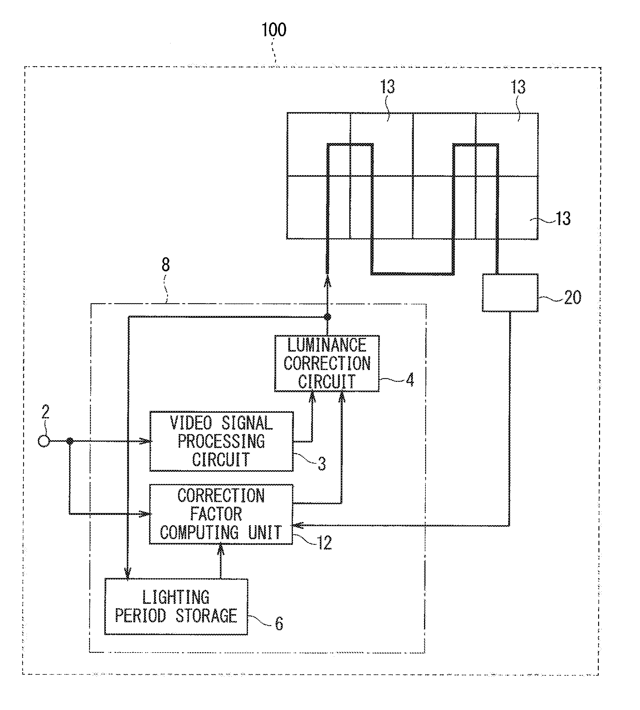
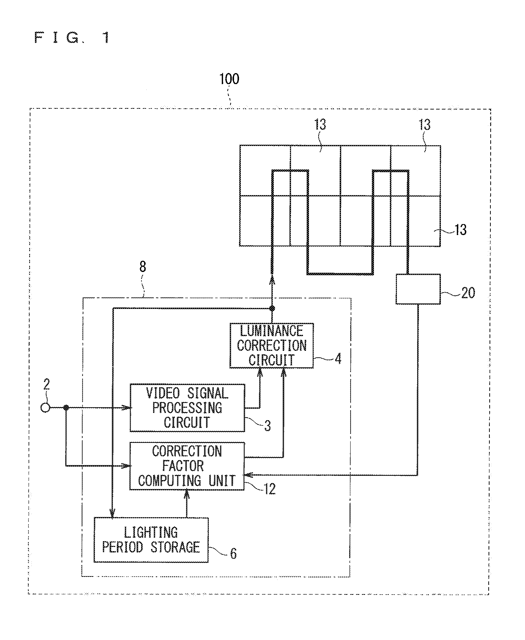
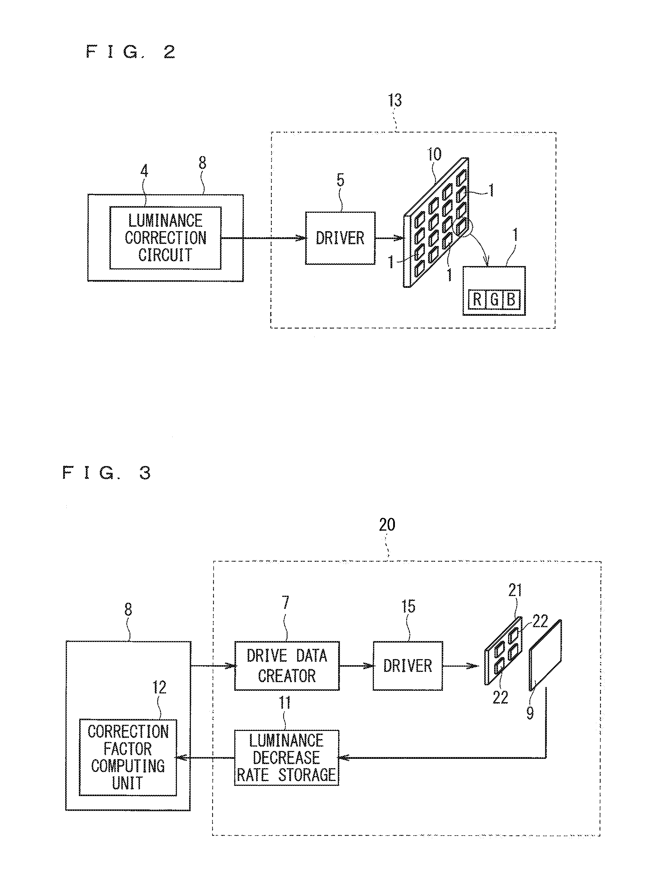
[0021]Description will be given on a first preferred embodiment of the present invention with reference to the drawings. FIG. 1 is a block diagram illustrating an LED display apparatus 100 according to the first preferred embodiment. FIG. 2 is a block diagram illustrating an LED display unit 13 of the LED display apparatus 100. FIG. 3 is a block diagram illustrating an LED aging unit 20 of the LED display apparatus 100.

[0022]As illustrated in FIG. 1, the LED display apparatus 100 includes a plurality of LED display units 13 (eight (2×4=8) units are illustrated in FIG. 1), an input terminal 2 for video signals, a video signal processing circuit 3, a luminance correction circuit 4 (a luminance corrector), a lighting period storage 6, a correction factor computing unit 12, and the LED aging unit 20. The video signal processing circuit 3, the correction factor computing unit 12, the luminance correction circuit 4, and the lighting period storage 6 are included in a controller 8.

[0023]Fi...

second preferred embodiment

[0059]The following description will be given on an LED display apparatus according to a second preferred embodiment. FIG. 11 is a graph for describing a method for correcting the luminance of the LED display apparatus 100 according to the second preferred embodiment. In the second preferred embodiment, the constituent components identical to the constituent components described in the first preferred embodiment are denoted by the same reference signs, and the description thereof is omitted.

[0060]As illustrated in FIG. 11, the luminance decrease rates of the individual LED 1 vary depending on the lighting rate. In the first preferred embodiment, the maximum duty ratio of the LEDs 1 of the LED display 10 and the maximum duty ratio of the LEDs 22 of the LED aging display 21 are set to be equal. However, the luminance decrease rate varies depending on the drive duty ratio of the LEDs. In this preferred embodiment, the drive data creator 7 creates the drive data having a plurality of du...


PUM


Abstract

An LED display apparatus includes an LED aging unit, a correction factor computing unit, and a luminance correction circuit. The LED aging unit includes an LED aging display that includes at least one second LED, a luminance measurer that measures luminance decrease rates of the second LED per color correspondently to lighting periods of first LEDs, and a luminance decrease rate storage that stores the luminance decrease rates. The correction factor computing unit computes correction factors for correcting luminances of the first LEDs per color in accordance with cumulative lighting periods of the first LEDs of corresponding colors and the luminance decrease rates of corresponding colors. The luminance correction circuit corrects the luminance of the first LEDs per color in accordance with the correction factors.

Description

FIELD OF THE INVENTION[0001]The present invention relates to LED display apparatuses and video display apparatuses including a plurality of LEDs arranged in a matrix and controlling flashing of individual LEDs to display video information, and more particularly relates to a technique for controlling luminances of the LEDs.DESCRIPTION OF THE BACKGROUND ART[0002]LED display apparatuses including LEDs (light-emitting diodes) are widely used to display, for example, advertisements indoors and outdoors owing to technical development associated with LEDs and reduction in cost of LEDs. Although the LED display apparatuses have been mainly used to display moving images such as natural pictures and animations, the LED display apparatuses for indoor use have reduced pixel pitches to achieve shorter visual distances, and thus are also used to display images on personal computers in meeting rooms, personal computers performing monitoring, and the like. In particular, the LED display apparatuses...

Claims


Application Information

Patent Timeline
IPC IPC(8): G09G5/10G09G5/14G09G5/04G09G3/32G09G3/20
CPCG09G5/10G09G3/32G09G3/2003G09G2300/026G09G5/14G09G2320/0233G09G5/04G09G3/2014G09G3/3208G09G2310/0235
Inventor MACHIDA, NAOYUKISHIBUE, SHIGENORIASAMURA, YOSHINORI
Owner MITSUBISHI ELECTRIC CORP
Why Eureka
Try Eureka