
RFID tag and RFID tag producing apparatus

a technology of producing apparatus and rfid tag, which is applied in the direction of record carriers used with machines, instruments, computing, etc., can solve the problems of reducing reducing aesthetic appearance, and bumps and indentations on label surfaces, so as to improve the visual quality of print on the rfid tag with print, improve the viewability of print, and reliably achieve easy-to-view print

Inactive Publication Date: 2009-08-13
BROTHER KOGYO KK
View PDF4 Cites 4 Cited by
  • Summary
  • Abstract
  • Description
  • Claims
  • Application Information

AI Technical Summary

Benefits of technology

[0008]An object of the present disclosure is to provide an RFID tag and RFID tag producing apparatus capable of improving the visual quality of the print and enhancing the aesthetic appearance.
[0010]The RFID tag of the first aspect forms a layered structure. In this layered structure, the section which includes the RFID circuit element forms a shape wherein the surrounding layers (base layer, print-receiving layer, and the like) curve around in the thickness direction in an amount equivalent to the thickness dimension of the loop antenna and the IC circuit part. As a result, in this section, protrusions, wrinkles, and the like (hereinafter, simply referred to as “protrusions, etc.,”) tend to readily occur on the outer appearance of the RFID tag. Particularly, in a case where a loop antenna is provided on the RFID circuit element, protrusions, etc., readily occur along the loop shape (square-frame shape, for example) of the loop coil.
[0011]In the first aspect, the RFID tag has a positional relationship such that the print area of the print-receiving layer is positioned on the inner peripheral side of the loop coil in the planar view. In consequence, print is printed only in the area corresponding to the inner peripheral side of the loop coil, and not in the area corresponding to the loop coil where protrusions, etc., readily occur as described above. With this arrangement, the poor viewability of print caused by light, i.e., shine and reflection, which occurs when print is printed on sections of protrusions, etc., is avoided, thereby making it possible to reliably realize easy-to-view print. As a result, the visual quality of the print is improved, thereby enhancing the aesthetic appearance.
[0013]In the second aspect, the produced RFID tag comprises a layered structure (in the thickness direction) that includes a tag medium (and a print-receiving medium) and an RFID circuit element. Then, in this layered structure, the section which includes the RFID circuit element forms a shape wherein the surrounding tag medium (and print-receiving medium) curves around in the thickness direction in an amount equivalent to the thickness dimension of the loop antenna and the IC circuit part. As a result, in this section, protrusions, wrinkles, and the like (hereinafter, simply referred to as “protrusions, etc.,”) tend to readily occur on the outer appearance of the RFID tag. Particularly, in a case where a loop antenna is provided on the RFID circuit element, protrusions, etc., readily occur along the loop shape (square-frame shape, for example) of the loop coil.
[0014]In the second aspect, the produced RFID tag with print has a positional relationship such that the print is positioned on the inner peripheral side of the loop coil in the planar view by the control performed by the printing control portion when the printing device performs printing. That is, printing is performed only in the area corresponding to the inner peripheral side of the loop coil, and not in the area corresponding to the loop coil where protrusions, etc., readily occur as described above. With this arrangement, the poor viewability of print caused by light, i.e., shine and reflection, which occurs when print is printed on sections of protrusions, etc., is avoided, thereby making it possible to reliably achieve easy-to-view print. As a result, the visual quality of the print on the RFID tag with print is improved, thereby enhancing the aesthetic appearance.

Problems solved by technology

In the RFID tag (RFID label) produced by such an RFID tag producing apparatus as described above, a difference sometimes occurs between the thickness of the RFID tag in the disposed area of the RFID circuit element and that of other areas, resulting in the formation of bumps and indentations on the label surface.
In JP, A, 2006-309557, because such points have not been taken into consideration, in a case where printing is performed at the disposed area of the RFID circuit element, the possibility exists that the bumps and indentations will decrease the visual quality of the print, thereby reducing the aesthetic appearance.

Method used


Image

  • RFID tag and RFID tag producing apparatus
  • RFID tag and RFID tag producing apparatus
  • RFID tag and RFID tag producing apparatus

Examples


Embodiment Construction

[0028]The following describes an embodiment of the present disclosure with reference to accompanying drawings.

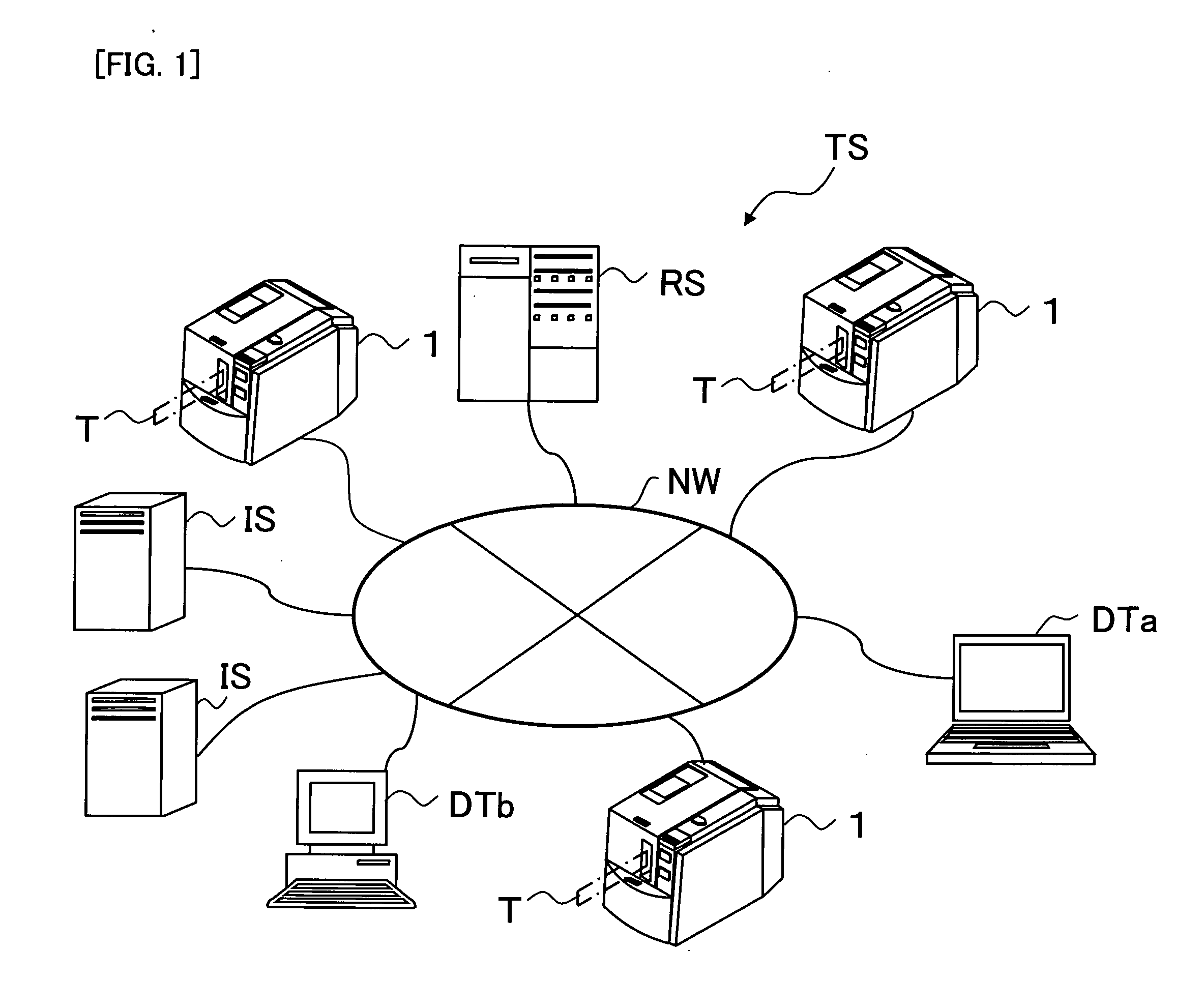
[0029]In an RFID label system TS shown in FIG. 1, a tag label producing apparatus 1 in the present embodiment comprises a route server RS, an information server IS, a terminal apparatus DTa, a general-purpose computer DTh, etc., via a communication network NW comprising a suitable communication line, etc.

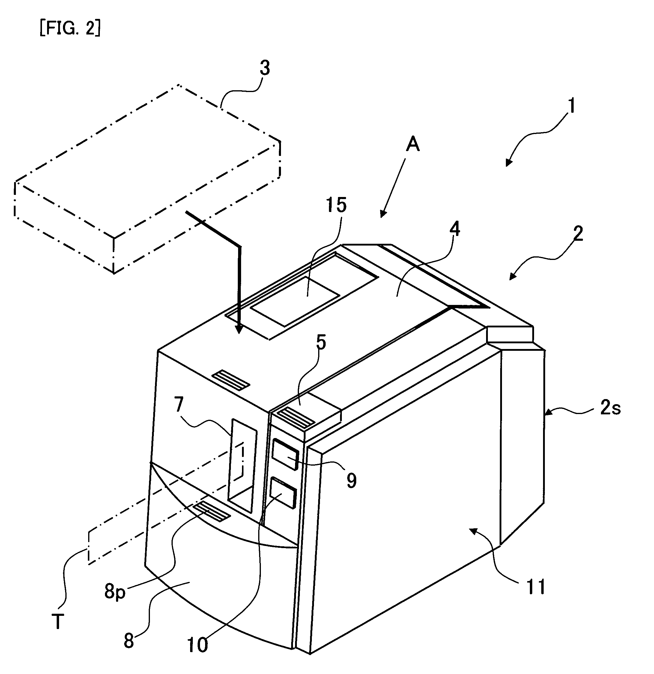
[0030]As shown in FIG. 2, the tag label producing apparatus 1 comprises an apparatus main body 2, and a cartridge 3 mounted to a cartridge holder 31 (refer to FIG. 3 described later) of the apparatus main body 2.

[0031]The apparatus main body 2 comprises a housing 2s of an overall rectangular shape as an outer shell (comprising an upper surface part, a lower surface part, a front surface part, a rear surface part, and both left and right side surface parts). On the upper surface part are provided an upper lid 4 and an upper lid operation button 5. On the front surface part ar...


PUM


Abstract

This disclosure discloses an RFID tag comprising: a base layer formed into a tape-shape or sheet-shape that disposes an RFID circuit element comprising an IC circuit part that stores information, and a loop antenna that transmits and receives information; a print-receiving layer on which print corresponding to information stored in the IC circuit part of the RFID circuit element is printable; and the print-receiving layer including a print area printable with a desired print disposed on an inner peripheral side of a loop coil of the loop antenna in a planar view of the RFID tag.

Description

CROSS-REFERENCE TO RELATED APPLICATIONS[0001]This application claims priority from JP 2008-19228, filed Jan. 30, 2008, the contents of which are hereby incorporated by reference.BACKGROUND[0002]1. Field[0003]The present disclosure relates to an RFID tag having an RFID circuit element comprising an IC circuit part configured to store information and a tag antenna configured to transmit and receive information, and an RFID tag producing apparatus for producing the same.[0004]2. Description of the Related Art[0005]An RFID (Radio Frequency Identification) system, for example, that reads / writes information between a small-sized RFID tag and a reader / writer (reading / writing apparatus) in a non-contact manner is known. For example, an RFID circuit element provided to a label-shaped or card-shaped RFID tag comprises an IC circuit part configured to store predetermined RFID tag information, and an antenna configured to transmit and receive information, connected to the IC circuit part. With ...

Claims


Application Information

Patent Timeline
Patent Type & Authority Applications(United States)
IPC IPC(8): G08B13/14
CPCG06K17/00G06K19/0776G06K17/0025
Inventor KATO, TSUTOMUMIWA, TAKAHIRO
Owner BROTHER KOGYO KK
Learn More