Thermally-assisted magnetic recording head including a main pole, a plasmon generator and two side shields

a magnetic recording and magnetic technology, applied in the field of magnetic recording heads, can solve the problems of increasing the coercivity of the recording medium, reducing the thermal stability of the magnetic field, and difficult to perform data writing with the existing magnetic head, so as to reduce the width of the track

Active Publication Date: 2016-11-24
HEADWAY TECH INC
View PDF2 Cites 19 Cited by
  • Summary
  • Abstract
  • Description
  • Claims
  • Application Information

AI Technical Summary

Benefits of technology

[0017]It is an object of the present invention to provide a thermally-assisted magnetic recording head with a reduced track width and a main pole capable of producing a write magnetic field of sufficient magnitude, and to provide a method of manufacturing such a thermally-assisted magnetic recording head.

Problems solved by technology

Making the magnetic fine particles smaller, however, causes the problem that the magnetic fine particles drop in the thermal stability of magnetization.
However, increasing the anisotropic energy of the magnetic fine particles leads to an increase in coercivity of the recording medium, and this makes it difficult to perform data writing with existing magnetic heads.
However, since the heat resulting from near-field light spreads on the recording medium by conduction, the thermal spot size becomes larger than the light spot size.
It is thus difficult to sufficiently reduce track width and thereby sufficiently increase recording density with the approach of reducing the light spot size alone.
This technique suffers from the problem that if the end face of the main pole and the end face of the plasmon generator are both reduced in width in order to achieve a smaller track width, the main pole becomes unable to pass much magnetic flux, thus becoming unable to produce a write magnetic field of sufficient magnitude from the end face of the main pole.
In this head, if the width of the pole tip is reduced in order to achieve a smaller track width, the write pole becomes unable to pass much magnetic flux, and consequently becomes unable to produce a write magnetic field of sufficient magnitude from the pole tip.

Method used


Image

  • Thermally-assisted magnetic recording head including a main pole, a plasmon generator and two side shields
  • Thermally-assisted magnetic recording head including a main pole, a plasmon generator and two side shields
  • Thermally-assisted magnetic recording head including a main pole, a plasmon generator and two side shields

Examples


first embodiment

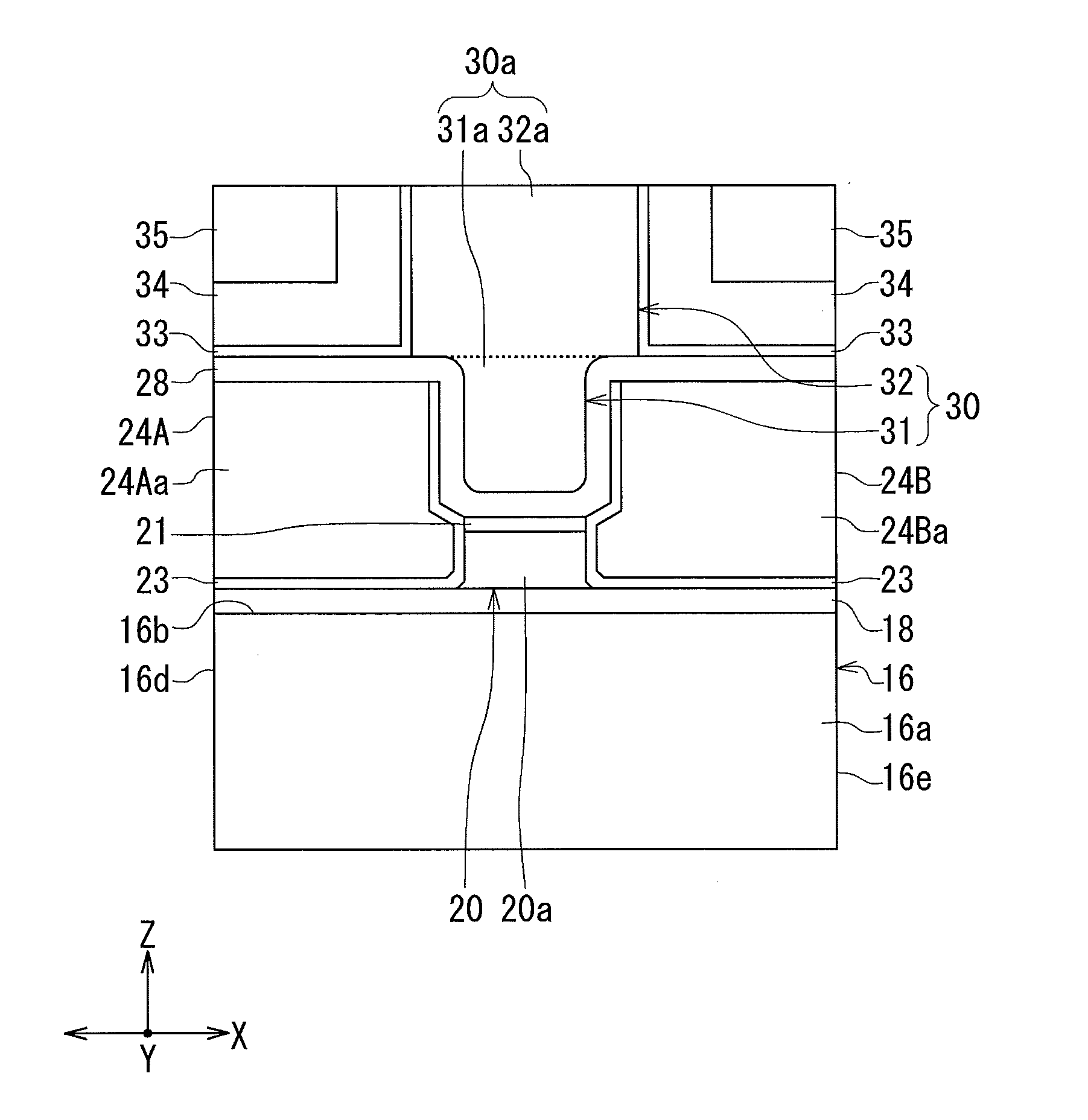
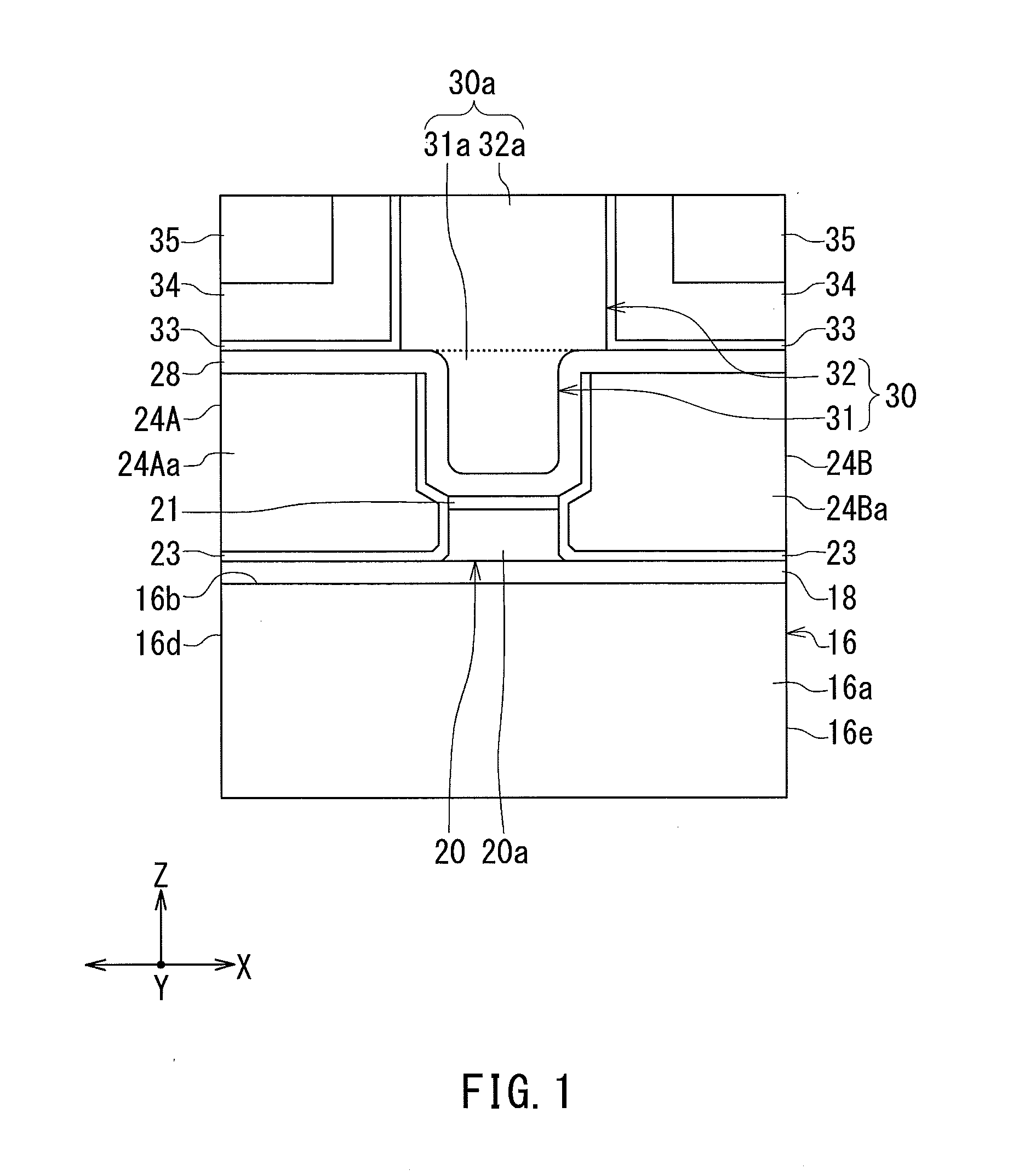
[0079]Preferred embodiments of the present invention will now be described in detail with reference to the drawings. First, reference is made to FIG. 1 to FIG. 8 to describe the configuration of a thermally-assisted magnetic recording head according to a first embodiment of the invention. FIG. 1 is a front view showing the main part of the thermally-assisted magnetic recording head. FIG. 2 is a cross-sectional view showing the main part of the thermally-assisted magnetic recording head. FIG. 3 is a plan view showing a core, a plasmon generator, a first side shield and a second side shield. FIG. 4 is a plan view showing a main pole, the first side shield, the second side shield, a first heat sink and a second heat sink. FIG. 5 is a cross-sectional view showing the configuration of the thermally-assisted magnetic recording head. FIG. 6 is a front view showing the medium facing surface of the thermally-assisted magnetic recording head. FIG. 7 is a plan view showing a first layer of a c...

second embodiment

[0188]A thermally-assisted magnetic recording head according to a second embodiment of the invention will now be described with reference to FIG. 21. FIG. 21 is a front view showing the main part of the thermally-assisted magnetic recording head according to the present embodiment. In the present embodiment, the first end face portion 31a of the front end face 30a of the main pole 30 is shaped differently than in the first embodiment. More specifically, in the present embodiment, the width of the first end face portion 31a in the track width direction (the X direction) increases with increasing distance from the near-field light generating surface 20a of the plasmon generator 20. Further, the first end face portion 31a has a first edge E1 closest to the near-field light generating surface 20a, and a second edge E2 located at the boundary between the first end face portion 31a and the second end face portion 32a. As shown in FIG. 21, the second edge E2 is longer than the first edge E...

third embodiment

[0200]A thermally-assisted magnetic recording head according to a third embodiment of the invention will now be described with reference to FIG. 28. FIG. 28 is a front view showing the main part of the thermally-assisted magnetic recording head according to the present embodiment. In the present embodiment, the first end face portion 31a of the front end face 30a of the main pole 30 is shaped differently than in the first embodiment. More specifically, in the present embodiment, the first end face portion 31a has a lower part closest to the plasmon generator 20, and an upper part located between the lower part and the second end face portion 32a of the front end face 30a of the main pole 30. The width of the lower part in the track width direction (the X direction) is substantially constant regardless of distance from the near-field light generating surface 20a of the plasmon generator 20, and is smaller than the width of the near-field light generating surface 20a in the track widt...


PUM

PropertyMeasurementUnit
temperatureaaaaaaaaaa
sizeaaaaaaaaaa
thicknessaaaaaaaaaa

Abstract

A thermally-assisted magnetic recording head includes a main pole, a plasmon generator, and first and second side shields. The main pole has a front end face located in the medium facing surface. The plasmon generator has a near-field light generating surface located in the medium facing surface. The front end face of the main pole includes a first end face portion, and a second end face portion greater in width than the first end face portion. The first and second side shields have first and second side shield end faces located on opposite sides of at least part of the near-field light generating surface and at least part of the first end face portion in the track width direction.

Description

BACKGROUND OF THE INVENTION[0001]1. Field of the Invention[0002]The present invention relates to a thermally-assisted magnetic recording head for use in thermally-assisted magnetic recording to write data on a recording medium with the coercivity thereof lowered by irradiating the recording medium with near-field light.[0003]2. Description of the Related Art[0004]Recently, magnetic recording devices such as magnetic disk drives have been improved in recording density, and thin-film magnetic heads and recording media of improved performance have been demanded accordingly. Among the thin-film magnetic heads, a composite thin-film magnetic head has been used widely. The composite thin-film magnetic head has such a structure that a read head unit including a magnetoresistive element (hereinafter, also referred to as MR element) for reading and a write head unit including an induction-type electromagnetic transducer for writing are stacked on a substrate. In a magnetic disk drive, the th...

Claims


Application Information

Patent Timeline
Patent Type & Authority Applications(United States)
IPC IPC(8): G11B5/31G11B5/48
CPCG11B5/315G11B5/3169G11B5/4866G11B2005/0021G11B5/314G11B11/10536G11B5/6088G11B11/10534G11B11/10543G11B5/3163
Inventor SASAKI, YOSHITAKAITO, HIROYUKITANEMURA, SHIGEKISATO, KAZUKIMAMIYA, HIDEOTAKANO, KENICHI
Owner HEADWAY TECH INC
Why Eureka
Try Eureka