High-frequency diaphragm and voice coil assembly

a high-frequency diaphragm and assembly technology, applied in the direction of frequency/directions obtaining arrangements, electrical transducers, electrical apparatus, etc., can solve the problems of amplifying sound in acoustically complex, phase difference between the received sounds, and high distortion, so as to facilitate sound reproduction, accurate control of the dome, and low distortion

a high-frequency diaphragm and assembly technology, applied in the direction of frequency/directions obtaining arrangements, electrical transducers, electrical apparatus, etc., can solve the problems of amplifying sound in acoustically complex, phase difference between the received sounds, and high distortion, so as to facilitate sound reproduction, accurate control of the dome, and low distortion

US20080013781A1Inactive Publication Date: 2008-01-17SAGREN ANDERS

Image

  • High-frequency diaphragm and voice coil assembly
  • High-frequency diaphragm and voice coil assembly
  • High-frequency diaphragm and voice coil assembly

Examples


Embodiment Construction

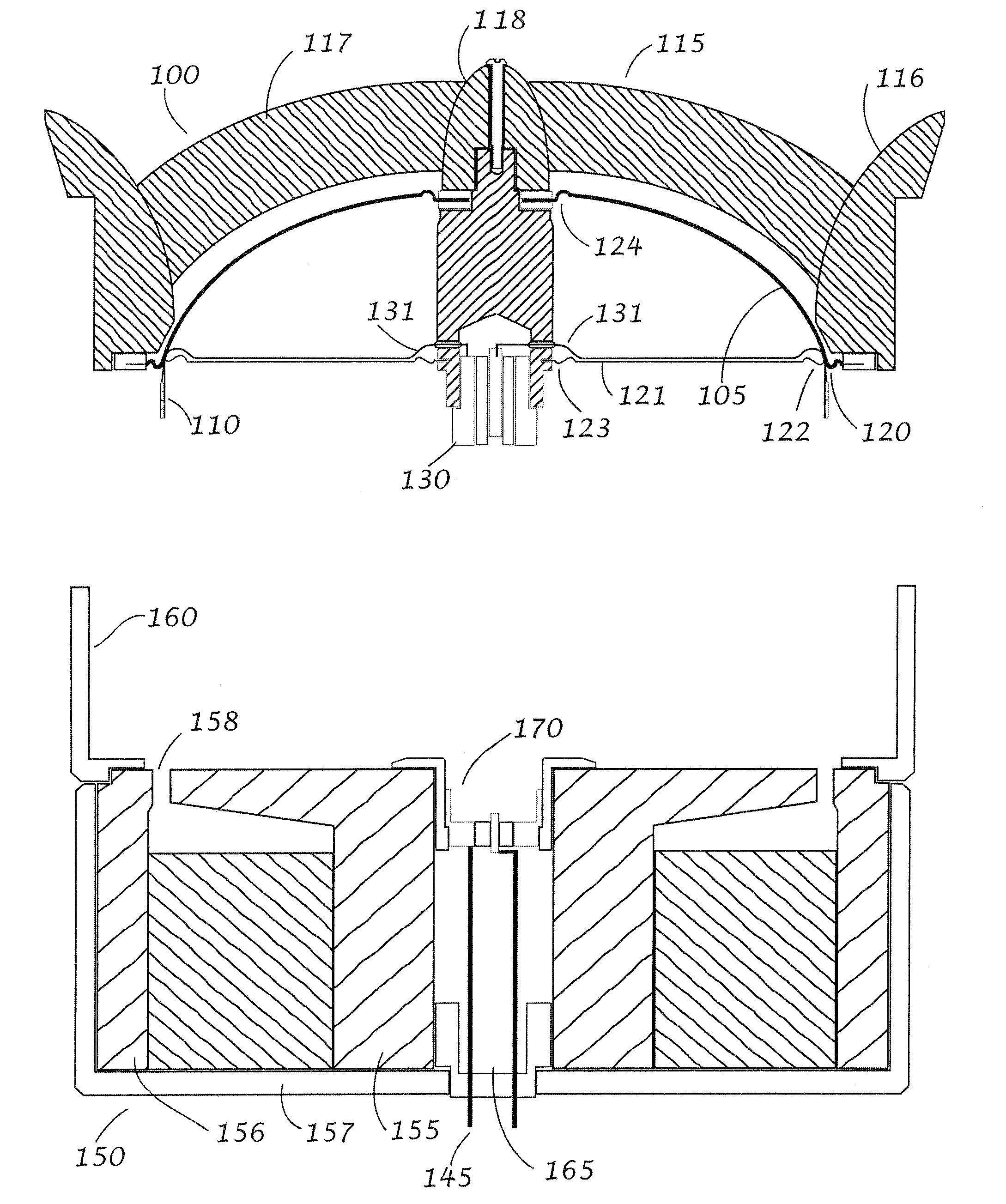
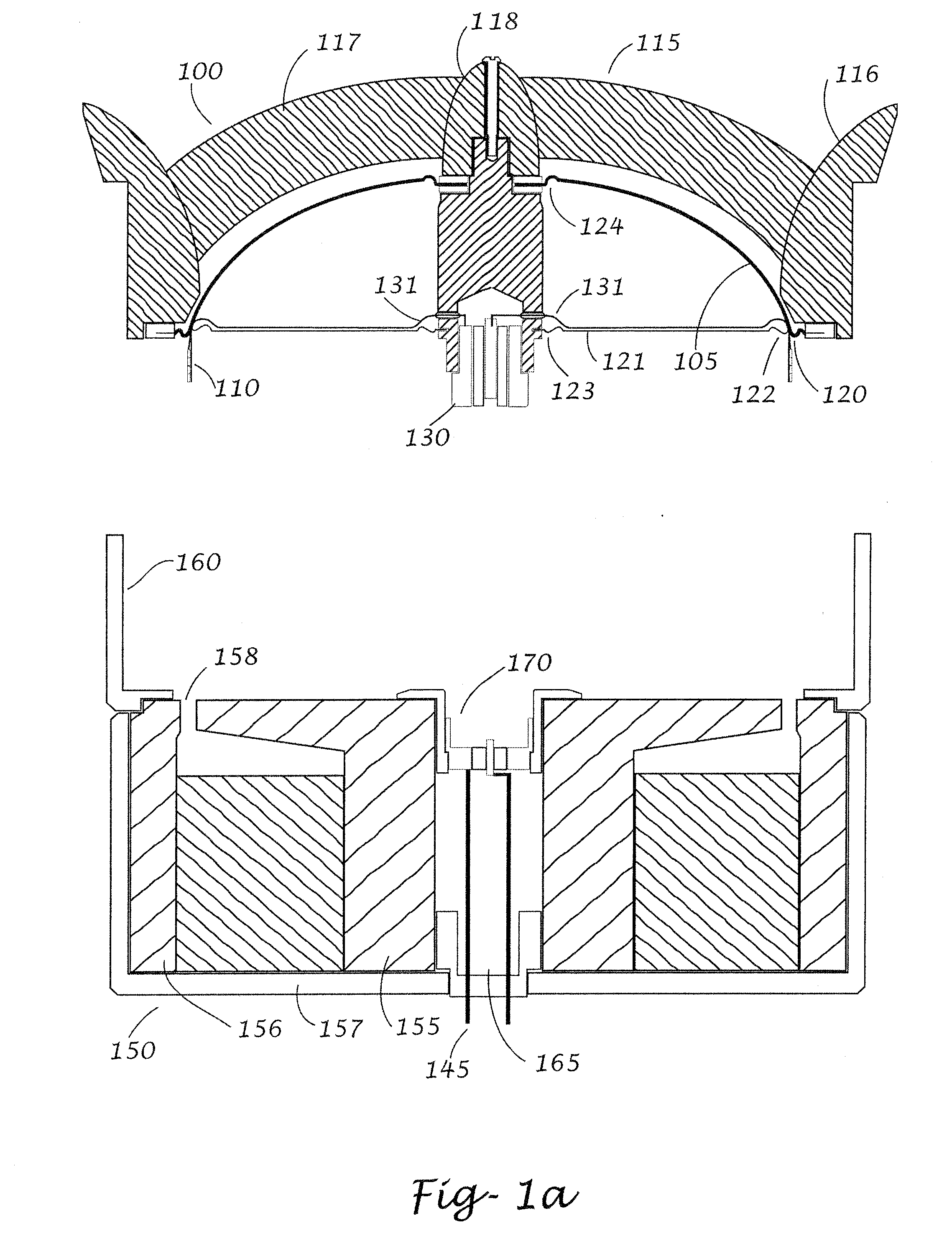
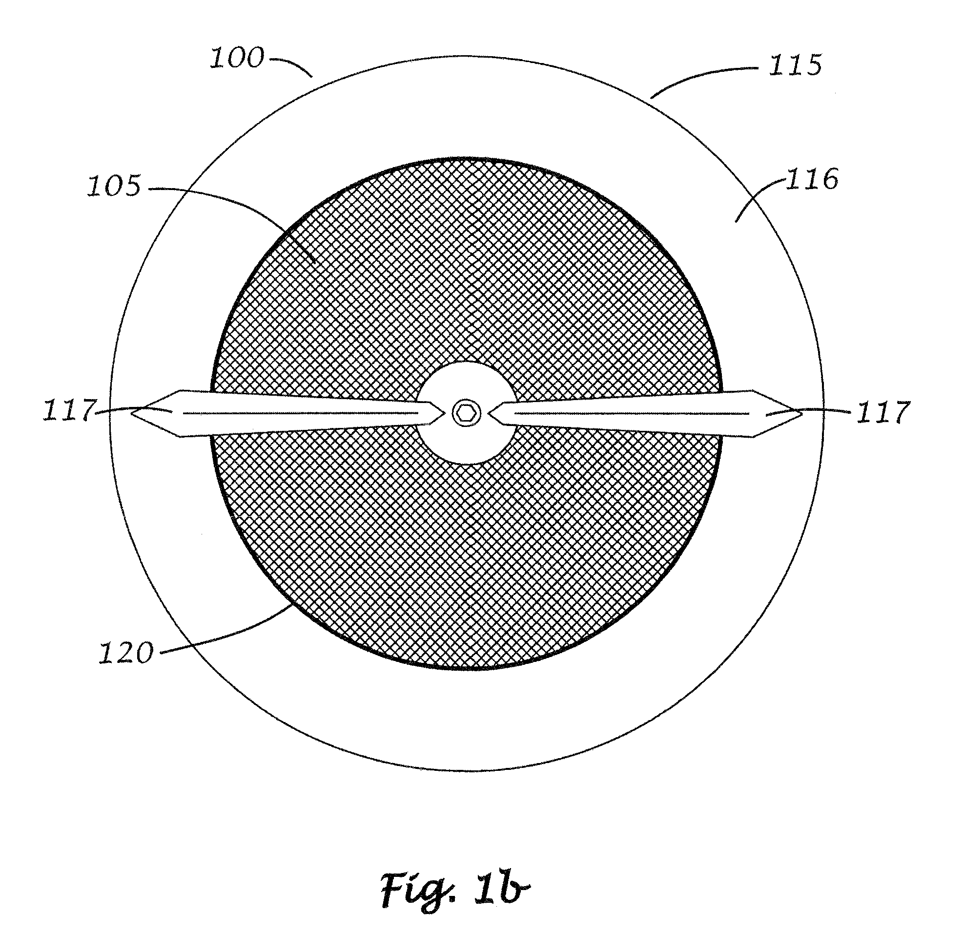
[0023] A first embodiment of the present invention will be described with reference to FIGS. 1a-d. The high frequency drive unit according to the invention comprises of a voice coil and diaphragm assembly 100 and a magnetic circuit assembly 150. Following the principles of U.S. Pat. No. 6,912,292 the two main parts, the voice coil and diaphragm assembly 105 and the magnetic circuit assembly 150 are separate modules and the voice coil and diaphragm assembly 105 is a self-supported module that can be removed and refitted to the magnetic circuit assembly 150.

[0024] The voice coil and diaphragm assembly 100 comprises a diaphragm 105, a voice coil 110 and a support structure 115. The support structure 115 comprises an annular part 116 defining the outer periphery of the voice coil and diaphragm assembly 100, and arranged to interact with a housing 160 of the magnetic circuit assembly 150. The support structure 115 is preferably formed to also serve as waveguide or a horn. This is indica...


PUM


Abstract

A high frequency drive unit comprising a dome-type diaphragm in a diaphragm and voice coil assembly. The diaphragm and voice coil assembly is particular suitable for use in compound loudspeakers with a plurality of drive units adapted to reproduce different part of the audio frequency spectra and which drive units are arranged in a co-axial configuration. The diaphragm of the diaphragm and voice coil assembly according to the invention has a circular cut out at its top defining an inner periphery of the diaphragm dome. The diaphragm is suspended on its inner periphery by a top annular suspension, at the outer periphery by an outer annular suspension extending outwards in a radial direction and at the outer periphery by an inner annular suspension extending inwards.

Description

TECHNICAL FIELD OF THE INVENTION [0001] The present invention relates electro-acoustic converters for sound reproduction, in particular, to loudspeaker high frequency drive units of dome-type and to compound loudspeakers with a plurality of drive units adapted to reproduce different part of the audio frequency spectra and which drive units are arranged in a co-axial configuration. BACKGROUND OF THE INVENTION [0002] In most loudspeaker system for reproducing a larger part of the audio frequency spectra at least two drive units are used. An example being a woofer used for reproduction of sounds in the low frequency bands and a tweeter used for the high frequency bands. The voice coils of the separate drive units are via a cross-over filter network connected to a power amplifier, which provide the electrical signals representing the sound to be reproduced. The purpose of the cross-over filter is to provide each drive unit with electrical signals corresponding to the audio frequency ran...

Claims


Application Information

Patent Timeline
17 Jan 2008
Publication
US20080013781A1
IPC
H04R9/06
CPC
H04R1/24; H04R7/127; H04R31/006; H04R9/043; H04R9/025; H04R7/12; H04R9/06
Inventors
SAGREN, ANDERS