Optimizing the distribution of electrical energy

a technology of electrical energy and distribution, applied in the field of distribution of electrical energy, can solve the problems of communication bottleneck, single point of failure, individual central management nodes configured as dispatchers entail disadvantages, etc., and achieve the effect of reducing individual disadvantages and increasing the outlay for their implementation

Active Publication Date: 2016-11-24
SIEMENS AG
View PDF13 Cites 9 Cited by
  • Summary
  • Abstract
  • Description
  • Claims
  • Application Information

AI Technical Summary

Problems solved by technology

However, an individual central management node configured as a dispatcher entails disadvantages such as communication bottlenecks, load spikes at one of the peer nodes or a single point of failure.
Moreover, it is possible for the central management node to yield only suboptimal results on account of limited time available to it, limited computing power and limited memory space.
However, these approaches only alleviate individual disadvantages, and moreover require an increased outlay for their implementation.

Method used


Image

  • Optimizing the distribution of electrical energy
  • Optimizing the distribution of electrical energy
  • Optimizing the distribution of electrical energy

Examples


Embodiment Construction

[0022]Elements having an identical function and effect are provided with the same reference signs in the figures.

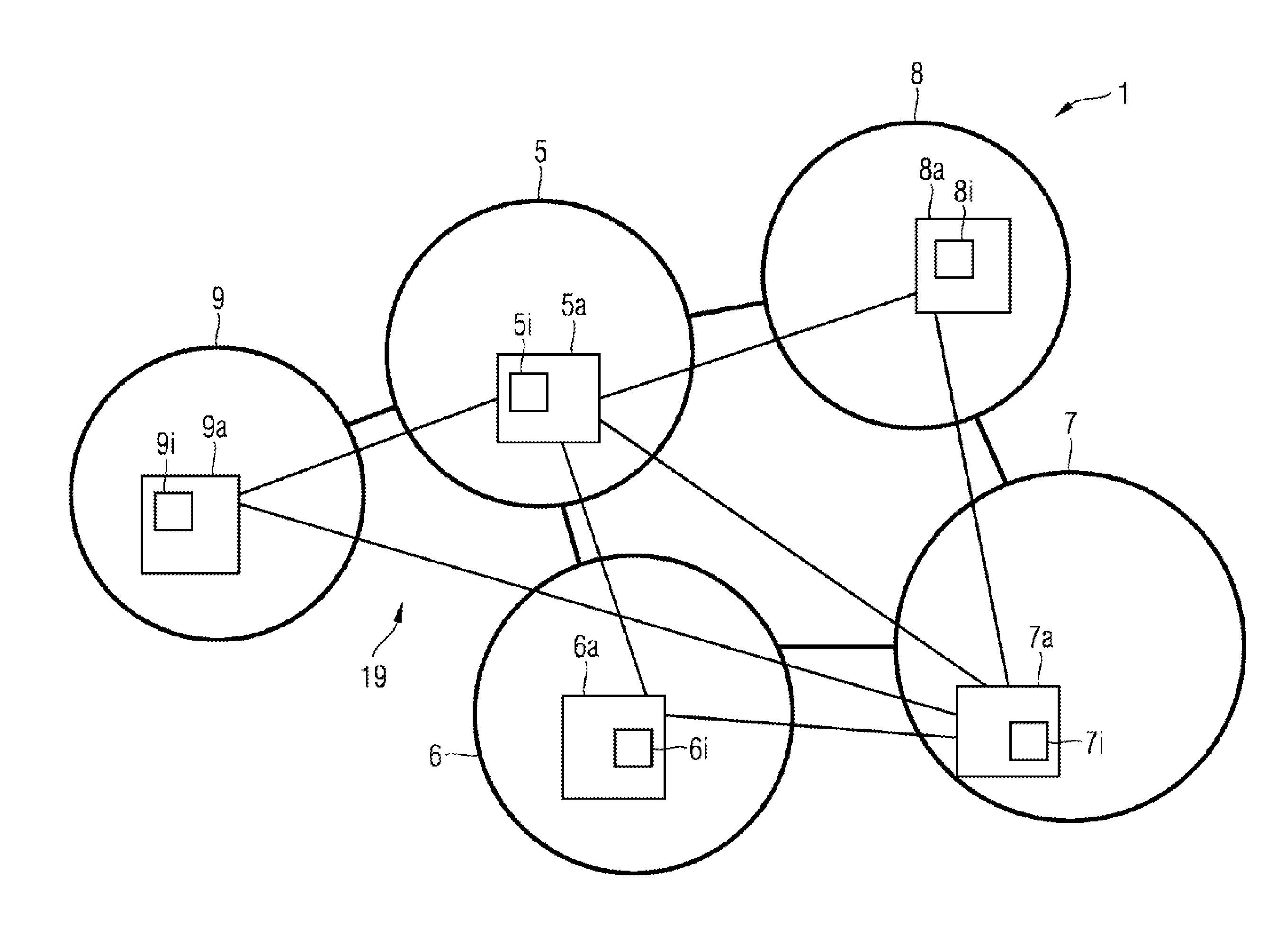
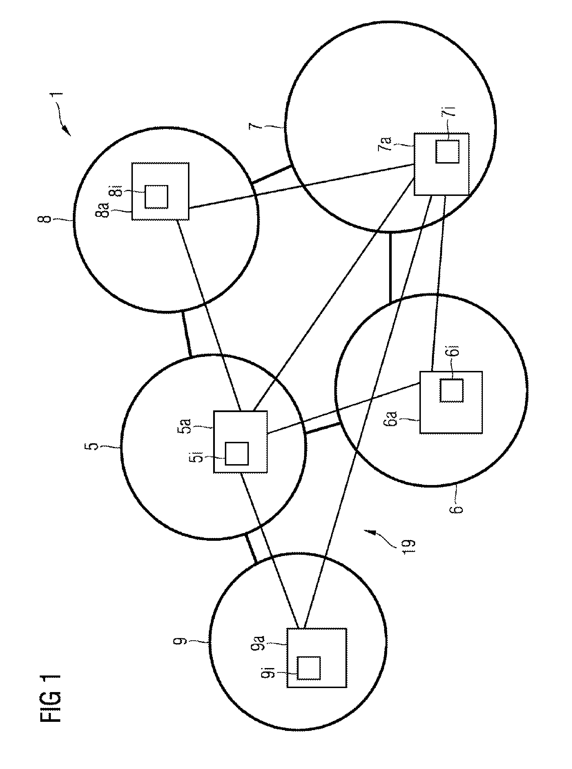
[0023]FIG. 1 shows a power grid 1, which is controlled by a data network 19, in accordance with one exemplary embodiment of the invention.

[0024]The power grid 1 is highlighted in FIG. 1 by the elements depicted using bold lines and comprises the autonomous grid regions 5, 6, 7, 8, 9 and electrical connections that connect the autonomous grid regions to one another. As illustrated in FIG. 1, not all of the autonomous grid regions need be connected to all of the other autonomous grid regions. Rather, there are diverse possibilities for interconnecting the autonomous grid regions. In reality, in a large power grid generally not all grid regions are connected to all grid regions, for cost reasons and on account of geographical conditions.

[0025]The data network 19 is highlighted in FIG. 1 by the elements depicted using lines of normal thickness and comprises the entities 5a, 6...


PUM


Abstract

The invention relates to methods and systems for optimizing the distribution of electrical energy in an electrical power supply system (I) which comprises autonomous supply system regions (5, 6, 7, 8, 9), comprising the method steps of:—receiving input data (II) by at least two dispatcher instances (5a, 7a), wherein the input data (II) represents energy intervals (5i, 6i, 7i, 8i, 9i) which are requested by the autonomous supply system regions (5, 6, 7, 8, 9);—calculating at least one solution (5s, 7s) of the distribution of electrical energy to the supply system regions (5, 6, 7, 8, 9) by each of the at least two dispatcher instances (5a, 7a);—selecting one of the calculated solutions (5s, 7s) for the distribution of electrical energy in the power supply system (I) by means of a leader election. The invention relates to the technical field of distributing electrical energy and can be used, for example, for smart grids.

Description

CROSS-REFERENCE TO RELATED APPLICATIONS[0001]This application claims priority to PCT Application No. PCT / EP2014 / 074177, having a filing date of Nov. 10, 2014, based off of DE Application No. 102014201555.3 having a filing date of Jan. 29, 2014, the entire contents of which are hereby incorporated by reference.FIELD OF TECHNOLOGY[0002]The following relates to the technical field of the distribution of electrical energy.BACKGROUND[0003]Algorithms regarding the leader election are known: http: / / en / wikipedia / org / wiki / Leader_election. DE 10 2011 078 045 A1 additionally discloses methods and devices for allocating quantities of energy.[0004]New energy grids, also referred to as soft grids, are composed of autonomous regions, which are also referred to as islands or grid regions and which are balanced among one another by means of the mutual distribution of the energy. This balancing can be realized by a node, which is also referred to as a dispatcher or optimizer and which, on the basis o...

Claims


Application Information

Patent Timeline
Patent Type & Authority Applications(United States)
IPC IPC(8): H02J13/00G05B13/02
CPCH02J13/0003H02J13/0006G05B13/021G06Q10/0631Y04S20/00Y02B90/20
Inventor HUND, JOHANNESKUNTSCHKE, RICHARD
Owner SIEMENS AG
Why Eureka
Try Eureka