Electronic lock assembly and lock thereof

a technology of electronic locks and lock parts, applied in the field of electronic locks and locks, can solve the problems of user inability to unlock locks, takes longer to unlock through this method, etc., and achieves the effects of preventing risk, increasing the efficiency of unlocking process, and increasing application possibilities

Inactive Publication Date: 2016-12-01
LINTEX
View PDF10 Cites 4 Cited by
  • Summary
  • Abstract
  • Description
  • Claims
  • Application Information

AI Technical Summary

Benefits of technology

[0007]The major object of the present invention is to provide an electronic lock assembly and a lock thereof which has a mechanical driving mechanism and an electronic driving mechanism and can be unlocked in two ways so as to prevent the risk that the lock is

Problems solved by technology

However, the structure mentioned above only includes a mechanical unlocking method, and it takes longer time to unlock through this method

Method used


Image

  • Electronic lock assembly and lock thereof
  • Electronic lock assembly and lock thereof
  • Electronic lock assembly and lock thereof

Examples


Embodiment Construction

[0019]The present invention will be clearer from the following description when viewed together with the accompanying drawings, which show, for purpose of illustrations only, the preferred embodiment in accordance with the present invention.

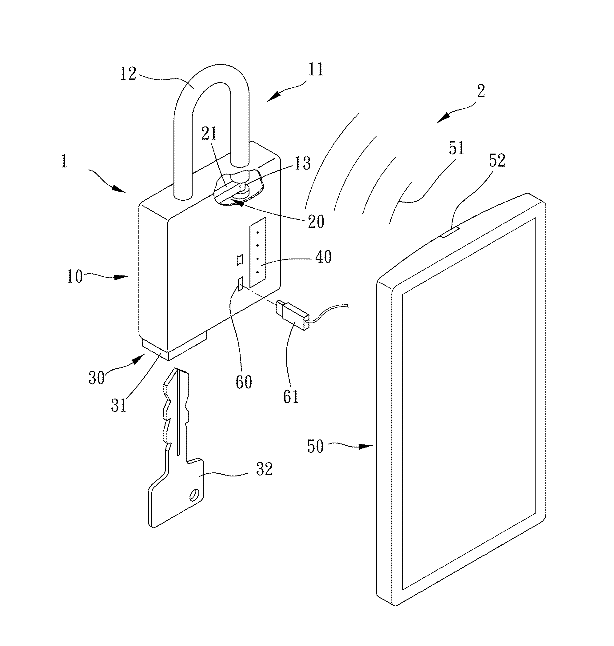
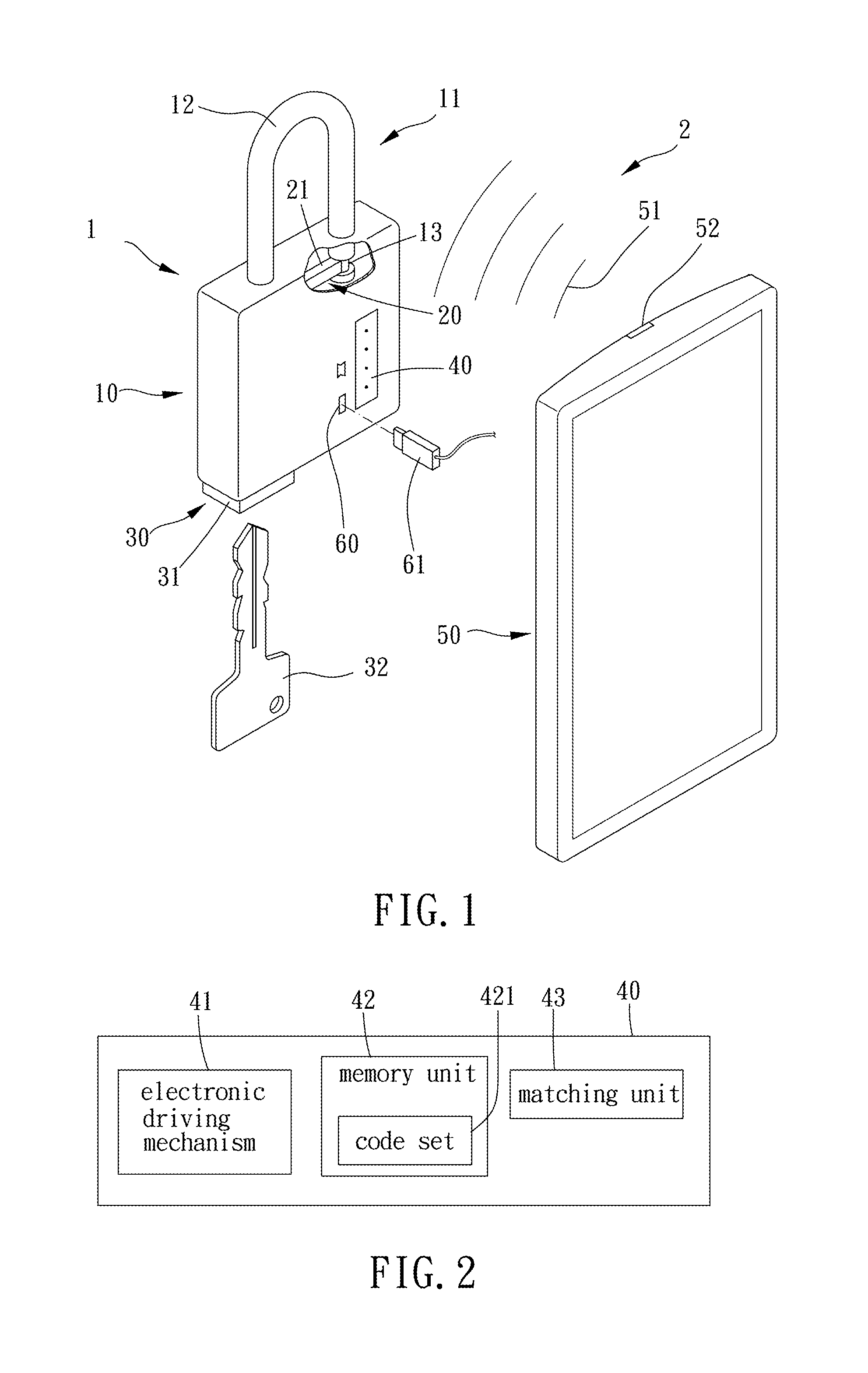
[0020]Please refer to FIGS. 1 to 3 for a first preferred embodiment of the present invention. A lock 1 includes a main body 10, a lock core 20, a mechanical driving mechanism 30 and an electronic unit 40.

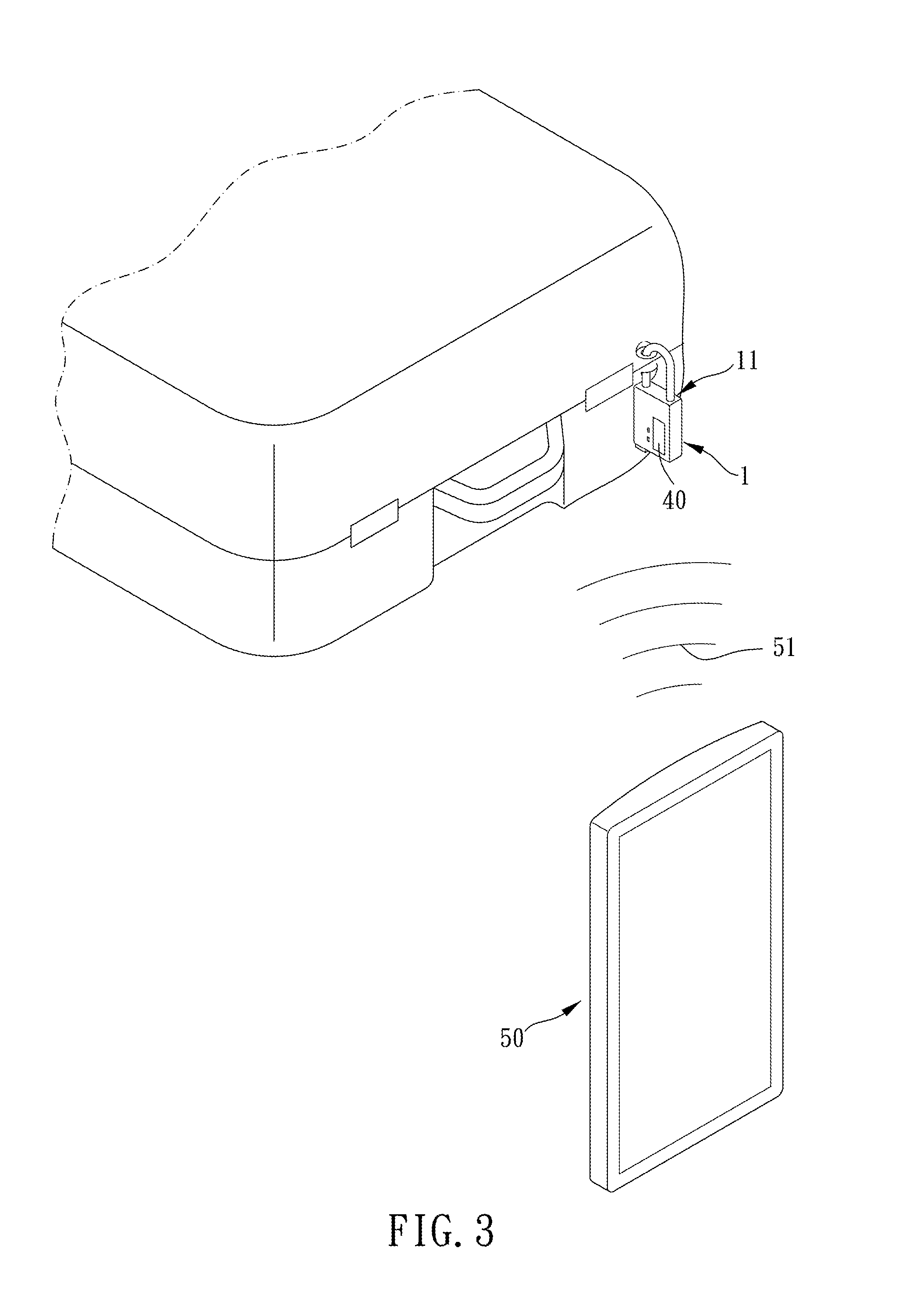
[0021]The main body 10 includes a locking mechanism 11 which is movable. Specifically, in this embodiment, the locking mechanism 11 may include a locking portion 12 (however, in other embodiments, the locking mechanism 11 may include a latch, a supporting member or a transformable member), the locking portion 12 can be provided for locking an object such as a luggage and making the object unable to be opened, and the locking portion 12 may lock or unlock the object through a key member.

[0022]The lock core 20 is disposed in the main body 10 and re...


PUM


Abstract

A lock is provided, including: a main body, including a locking mechanism which is movable; a mechanical driving mechanism, for being operated to dismiss the locking mechanism from a locked state; an electronic unit, disposed on the main body for receiving an unlocking signal from an electronic device, the electronic unit including an electronic driving mechanism; wherein when the electronic unit receives the unlocking signal, the electronic driving mechanism dismisses the locking mechanism from the locked state. An electronic lock assembly is further provided, including the lock mentioned above, the electronic lock assembly further including an electronic device, the electronic device including a signal sending device which is capable of sending the unlocking signal.

Description

BACKGROUND OF THE INVENTION[0001]1. Field of the Invention[0002]The present invention relates to a lock, and more particularly to an electronic lock assembly and a lock thereof.[0003]2. Description of the Prior Art[0004]Usually, a conventional lock includes a locking mechanism, a lock core and a driving mechanism, and a user can use, for example, a key to drive the driving mechanism so as to comove the lock core to control the locking mechanism to lock or unlock the lock.[0005]However, the structure mentioned above only includes a mechanical unlocking method, and it takes longer time to unlock through this method. The mechanical unlocking method often needs to cooperate with the key; therefore, when the key gets lost, the user cannot unlock the lock. In addition, another unlocking method is needed for different users to use in accordance with different requirements.[0006]The present invention has arisen to mitigate and / or obviate the afore-described disadvantages.SUMMARY OF THE INVE...

Claims


Application Information

Patent Timeline
IPC IPC(8): G07C9/00E05B47/00
CPCG07C9/00182G07C2009/0023E05B2047/0084E05B47/0001G07C9/00896E05B67/00E05B2047/0094E05B2047/0086E05B2047/0095E05B47/00E05B67/24E05B73/0082
Inventor LIN, CHIA-SHENG
Owner LINTEX
Why Eureka
Try Eureka